Clockwork PicoCalc · Volume 4
PicoCalc Volume 4 — BIOS, Bootloaders & SD Card
STM32 keyboard firmware, the UF2 Loader, the SD multi-boot system, and six ways to put a UF2 onto the device
Contents
1. About this Volume
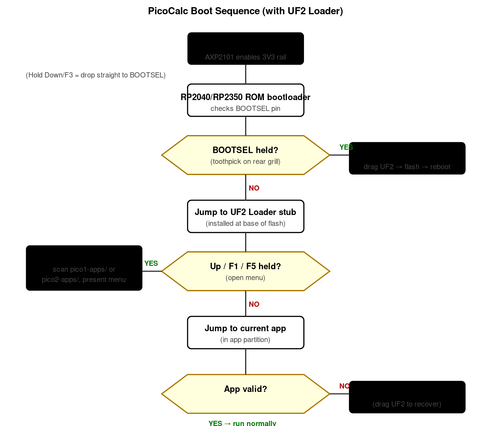
Figure 1.0 — PicoCalc boot sequence. Source: UF2 Loader README + observed behavior, §3-§4.
This volume covers the firmware layer between bare silicon and the user-facing programming stacks. Three subsystems live here: the STM32F103R8T6 keyboard coprocessor firmware (the “BIOS”), the PicoCalc UF2 Loader (the SD-resident bootloader), and the microSD card layout that the loader reads at boot. All three matter because none of the user-facing stacks (PicoMite, MicroPython, etc., covered in Volume 5) work without them being correct.
The BIOS deep-dive includes the four update procedures (DFU, UF2-forwarding, Arduino IDE rebuild, SWD recovery) and the v1.4-brick story with its root-cause analysis. The UF2 Loader chapter covers the install-from-BOOTSEL flow on both Pico 1 and Pico 2, the USB Mass Storage feature, and recovery if the bootloader itself gets corrupted.
2. The PicoCalc BIOS — Deep Dive
The “BIOS” of the PicoCalc has nothing to do with PC BIOS or UEFI. The community uses the term to refer to the firmware running on the STM32F103R8T6 keyboard coprocessor on the carrier board. That STM32 is responsible for scanning the 67-key matrix, debouncing the power button, driving the LCD backlight PWM, driving the keyboard backlight PWM, talking to the AXP2101 over I²C for battery telemetry, and presenting itself as an I²C slave at address 0x1F for the Pico to read keystrokes and battery state.
The Pico itself does not have a “BIOS” in any meaningful sense. When this document says BIOS, it means the STM32 firmware.
2.1 What the BIOS does in practice
On power-up the AXP2101 brings up the 3.3 V rail and the STM32 boots from internal flash. From the moment it has a clock, the STM32 is doing five jobs in parallel:
- Keyboard matrix scan. Eight rows × eleven columns, scanned at ~1 kHz, debounced and translated into key events.
- Power button monitoring. Long-press to power on (~1 second), long-press to power off (~3 seconds). Short-press is a chord modifier that the keyboard firmware can interpret.
- Backlight PWM. Two channels — LCD backlight and keyboard backlight. Default values are stored in STM32 flash and adjusted via I²C commands from the Pico.
- AXP2101 telemetry. Polls battery voltage, charge current, and charge state at ~1 Hz. Cached values are exposed over I²C to the Pico.
- I²C slave protocol. The Pico is the I²C master; the STM32 responds to a small command set documented in the official
clockworkpi/PicoCalcrepo and, more accurately, in DeepWiki at https://deepwiki.com/clockworkpi/PicoCalc.
Because the STM32 owns the keyboard end-to-end, the Pico’s view of input is “ask the STM32 over I²C, get a key event.” The Pico cannot reach the matrix directly. This is why a buggy BIOS update can render the device totally non-responsive even though the Pico itself is fine.
2.2 BIOS version history
| Version | Notable changes | Backward-compatible? |
|---|---|---|
| 1.0 | Original kit firmware | — |
| 1.1 | Battery telemetry fix (over-reported voltage by ~50 mV) | Yes |
| 1.2 | Keyboard event buffering improvements | Yes; uLisp v1.1 needs ≥1.2 |
| 1.3 | Auto-power-off timer added (configurable via I²C) | Yes |
| 1.4 | Restart-loop bugfix for MicroPython and uLisp; backlight PWM range expanded | Mostly — see §2.3 |
The community-maintained source for current binaries is the Code/picocalc_keyboard/ directory in https://github.com/clockworkpi/PicoCalc. Note: at one point the STM32 firmware binaries were committed to the repo as ELF files instead of raw .bin files (issue #44). Make sure you have an actual .bin (or .dfu) before flashing.
2.3 The 1.4 brick story
A subset of users reported total keyboard failure after flashing the v1.4 binary published in mid-2025. The reproducible failure mode was:
- STM32CubeProgrammer reports “Operation Exceeds Memory Limits” during the flash step.
- The flashing process appears to complete despite the error.
- On next power-on, the keyboard is unresponsive.
Root cause analysis on the forum traces it to the binary having been compiled against a flash-layout assumption that doesn’t match every STM32F103R8T6 part variant. Recovery is via SWD (see §2.7); the device is not hard-bricked. This is documented in https://forum.clockworkpi.com/t/new-keyboard-bios-1-4/19258 with the failure mode, root cause, and recovery procedure.
Practical guidance:
- If you have BIOS 1.3 or earlier and your keyboard works, do not blindly upgrade to 1.4. The benefits are minor unless you specifically need the MicroPython restart-loop fix.
- If you must upgrade, have a Pico Probe (or any SWD-capable adapter) on hand before you start. The probe is documented in §2.7.
- The 1.4 fix has since been re-issued; check the date on the binary you download. Anything dated after late-2025 should be safe.
2.4 Update path A — DFU over USB-C
This is the documented official procedure and works on all known-good binaries. You need:
- A USB-C cable that supports data (charge-only cables will not work).
- A Windows, Mac, or Linux host.
- STM32CubeProgrammer (free from STMicroelectronics: https://www.st.com/en/development-tools/stm32cubeprog.html).
- The
.binor.dfufile for the BIOS version you want.
Procedure:
- Power the PicoCalc off. Hold the power button for 3 seconds.
- Open the rear shell. Unscrew the four hex bolts; remove the rear half so the carrier PCB is accessible.
- Locate switch SW107. It’s a 4-position DIP switch on the carrier. The silkscreen labels it. Flip position 1 to ON. This routes the STM32’s USB lines to the USB-C connector on the case in DFU mode.
- Connect USB-C to the host.
- Hold the BOOT button (also on the carrier — there’s a labelled tactile switch near the STM32) while pressing the RESET button briefly. Release RESET, then release BOOT. The STM32 is now in DFU bootloader mode.
- On the host, launch STM32CubeProgrammer. Select USB as the connection type. Click Connect. The device should appear as “STM32 BOOTLOADER”.
- Click Open file and select the
.bin. The address should be0x08000000(start of STM32F103 flash). - Click Download. Wait for “File download complete.”
- Click Disconnect.
- Flip SW107 position 1 back to OFF.
- Press RESET on the carrier.
- Re-attach the rear shell.
- Power on the PicoCalc and verify the keyboard works.
If step 8 reports “Operation Exceeds Memory Limits,” stop immediately — the binary is not compatible. Do not continue; recover the previous BIOS via SWD (§2.7).
2.5 Update path B — UF2 forwarding from the Pico
A community alternative routes the BIOS update through the Pico instead of requiring DFU mode. The Pico runs a small “BIOS updater” UF2 that talks to the STM32 over the existing I²C bus and pushes the new firmware to it.
- Source:
picocalc-bios-updaterrepos on GitHub. Search for the latest fork. - Pros: no DIP switch flip, no STM32CubeProgrammer needed, no host required other than a freshly-flashed Pico.
- Cons: requires the existing BIOS to be functional (so it cannot rescue a brick); the updater UF2 is built specifically for one BIOS version pair (source → target).
Use this path for upgrades when you already have a working BIOS — it’s faster than path A. Use path A or path C for first-time BIOS work or recovery.
2.6 Update path C — Arduino IDE STM32duino (rebuild from source)
If you want to modify the BIOS — adding a custom keymap, tweaking backlight curves, exposing new I²C registers — you compile from source with the Arduino IDE plus the STM32duino board package.
- STM32duino board package: add board manager URL
https://github.com/stm32duino/BoardManagerFiles/raw/main/package_stmicroelectronics_index.json. Install the “STM32 Cores” package. - Source:
Code/picocalc_keyboard/in https://github.com/clockworkpi/PicoCalc. - Board target: select Generic STM32F1 series → BluePill F103R8 in Tools → Board.
- Upload method: STM32CubeProgrammer (DFU) — same hardware procedure as path A.
- Programming language: C / Arduino. The codebase is small (~3000 lines).
This path is also the recovery path if you’ve authored a custom BIOS and need to revert to stock — clone the official source, build a stock binary, flash via DFU.
2.7 Update path D — SWD recovery (the brick rescue)
If a flash went wrong and the device is unresponsive, SWD is the always-available rescue. You need:
- A Raspberry Pi Debug Probe (~$12 from official Raspberry Pi vendors) or any SWD-capable adapter (Black Magic Probe, J-Link, ST-Link V2 clone).
- Three jumper wires (SWDIO, SWCLK, GND).
- A working stock BIOS binary (keep one on disk — never flash a new BIOS without keeping a copy of the previous one).
Procedure:
- Locate the SWD test points on the carrier PCB: SWDIO, SWCLK, and GND, near the STM32. The silkscreen labels them.
- Wire up the probe: SWDIO ↔ SWDIO, SWCLK ↔ SWCLK, GND ↔ GND. Power the PicoCalc from its battery or USB-C — the probe does not power the target.
- On the host, launch STM32CubeProgrammer. Select ST-LINK (or whatever your probe presents as) as the connection type.
- Click Connect. If “Cannot connect” → check wiring and that the PicoCalc is powered.
- Erase the chip: Erasing → Full chip erase. This removes the broken BIOS completely.
- Flash the known-good binary: Open file → select the binary → Download to
0x08000000. - Disconnect. The device will boot into the recovered BIOS on the next power cycle.
The Odd Inventor “PicoCalc back with Pico Probe port” 3D-printable case (mentioned in §3.5) keeps the probe permanently mounted so this entire recovery is just three button presses on STM32CubeProgrammer instead of a teardown. If you do BIOS work regularly, this is the upgrade.
2.8 Verifying a successful BIOS update
After any BIOS update, run through this checklist before reassembling the case:
- Power on. Hold the power button for ~1 second. Backlight should come up; some boot text should appear (the currently-flashed Pico app, or BOOTSEL drive notification if there’s no app).
- Type a few keys. All four corners (Q, P, Z, /), the spacebar, and Enter. Verify each appears.
- Function keys. F1–F10 should each print something on a stack that exposes them (PicoMite’s CLS will clear-screen on F1 etc.; MicroPython treats them as escape sequences).
- D-pad. Up, Down, Left, Right.
- Backlight slider. On stock BIOS the keyboard combo is Fn + Up/Down. Verify it cycles brightness.
- Battery readout. Run a small MicroPython or PicoMite script that reads the battery percentage from the I²C interface — it should match a multimeter reading on the cells (within 5%).
If anything fails, do not reassemble — re-flash or revert before closing up.
2.9 Custom keymaps
Stock BIOS exposes a fixed US-QWERTY layout. If you want Dvorak, Colemak, AZERTY, or a custom layout, you have two choices:
- Modify the BIOS at the STM32 level. The
picocalc_keyboardsource has the keymap as aconstlookup table; change the table, rebuild via path C above, flash. This is the cleanest solution because every stack on the Pico sees the new layout transparently. - Remap on the Pico side. PicoMite, MicroPython, and the C SDK all expose a “keypress event” that you can intercept and remap before it reaches the user-visible API. This is per-stack and fragile — switching firmware loses your remap.
For a permanent custom layout, the BIOS approach is preferable. Forum thread https://forum.clockworkpi.com/t/custom-picocalc-bios-keyboard-firmware/17292 has working Dvorak and Colemak forks of the stock BIOS that you can flash directly without rebuilding.
3. SD Card Setup and Initial Bootload
The SD card is more than just storage on the PicoCalc — with the multi-boot bootloader installed, it functions as the device’s “operating system disk,” holding the bootloader UI, the per-architecture app folders, and any persistent state. This chapter covers the card from raw out-of-the-package to bootable, with every gotcha that has tripped users on the forum.
3.1 Card sizing and brand
The official kit ships with a 32 GB microSD pre-loaded with the multi-boot bundle. The actual size requirement is much smaller — the bundle itself is well under 200 MB — but a larger card lets you keep dozens of UF2s, ROMs, samples, and PicoMite source files on the same volume.
Practical sizing guidance:
- 8–32 GB is the sweet spot. Cheap, universally available, fast enough for SPI-attached SD on the Pico, large enough for the entire multi-boot bundle plus ROMs and samples with room to spare.
- 64–128 GB works but must be reformatted to FAT32 (covered in §3.3). Cards in this size class ship pre-formatted exFAT, which the multi-boot bootloader does not currently mount.
- 256 GB+ is unnecessarily large and historically problematic. The card-side controllers in larger cards sometimes mis-report sector counts to the Pico’s SPI driver. Search the forum at https://forum.clockworkpi.com/c/picocalc/?q=SD%20card for current incompatibility reports before buying.
Brand recommendations from the community: SanDisk Ultra, Samsung Evo Plus, Kingston Canvas Select Plus. Avoid no-name cards from marketplace listings — the failure mode is usually silent corruption after a few weeks of write activity.
3.2 Format choice — why FAT32 and not exFAT
The multi-boot bootloader uses petit-FatFs / FatFs to read the SD card. FatFs supports FAT12, FAT16, and FAT32; the firmware is built with exFAT support disabled to keep the bootloader small (exFAT support adds ~40 KB of code).
This means:
- Cards 32 GB or smaller: ship pre-formatted FAT32 — no action needed.
- Cards 64 GB or larger: ship pre-formatted exFAT — must be reformatted to FAT32 before first use.
How to reformat a 64+ GB card to FAT32 on Windows: the built-in Windows formatter refuses to format >32 GB volumes as FAT32. Use one of:
- Rufus (https://rufus.ie): plug in card, launch Rufus, select the card, choose “Large FAT32” as filesystem, click Start. Done in under a minute.
- fat32format by Ridgecrop (http://www.ridgecrop.demon.co.uk/index.htm?guiformat.htm): single-purpose GUI tool, also works.
On macOS Disk Utility can format any card to FAT32 via Erase → MS-DOS (FAT). On Linux use sudo mkfs.vfat -F 32 /dev/sdX or the GNOME Disks GUI.
3.3 The default layout
After formatting, the card layout for a multi-boot setup is:
/                              ← root of the FAT32 volume
├── BOOT2040.UF2               ← UF2 Loader UI for Pico 1 (RP2040)
├── BOOT2350.UF2               ← UF2 Loader UI for Pico 2 (RP2350)
├── pico1-apps/                ← UF2 files to launch on Pico 1
│   ├── picomite_basic.uf2
│   ├── micropython.uf2
│   ├── ulisp.uf2
│   ├── picolua.uf2
│   ├── nes_emu.uf2
│   └── ...
└── pico2-apps/                ← UF2 files to launch on Pico 2
    ├── picomite_basic_rp2350.uf2
    ├── micropython_rp2350.uf2
    ├── peanutgb.uf2
    ├── picoware.uf2
    └── ...
Why two folders? UF2 files are architecture-specific. A UF2 built for RP2040 will not run on RP2350 (different vector tables, different linker layout). The bootloader checks which Pico is currently in the socket and shows only the matching folder’s contents.
You can keep a Pico 1 and Pico 2 sharing the same SD card simultaneously — the bootloader DTRT.
The factory bundle additionally has, at the tail of the card (not visible in the FAT32 partition), a 32 MB raw partition that is the FUZIX root filesystem. That partition is created by the factory image; if you reformat the entire card, FUZIX won’t have a root and the FUZIX UF2 will hang at boot. Recreate it with dd if=/dev/zero of=/dev/sdX bs=1M seek=$((CARDSIZE-32)) count=32 (Linux) followed by writing the FUZIX root image.
3.4 First-boot from the factory image
If you have not touched the card since unboxing:
- Power on with no Pico in the socket → BOOTSEL drive appears on USB-C. Skip; this is not the right scenario.
- Power on with the factory-flashed Pico 1 H module in the socket and the factory SD inserted.
- The PicoCalc loads the factory UF2 Loader, displays a numbered menu of available apps.
- Use Up/Down to select. Press Enter to launch.
- Hold Down or F3 during power-on to drop the Pico into BOOTSEL mode (rear-grill USB-C appears as
RPI-RP2).
If the SD card is missing, blank, or mis-formatted, the device falls into BOOTSEL mode automatically — there’s no “no SD” error screen.
3.5 Rebuilding the multi-boot bundle from scratch
If you need to recreate the SD layout (lost the original card, formatted accidentally, want a clean start):
- Format the card FAT32 using one of the tools in §3.2.
- Download the UF2 Loader release from https://github.com/pelrun/uf2loader/releases. You want both
BOOT2040.UF2andBOOT2350.UF2. - Copy
BOOT2040.UF2andBOOT2350.UF2to the root of the card. - Create empty folders:
pico1-apps/andpico2-apps/. - Add at least one UF2 to each folder — typically PicoMite or MicroPython for that architecture. Without an app present, the bootloader shows an empty menu.
- Flash the bootloader to the Pico itself (one-time, per Pico module):
bootloader_pico.uf2for Pico 1 orbootloader_pico2.uf2for Pico 2 — drag onto the BOOTSEL drive. The Pico now boots into the SD menu by default. - Eject the SD properly from the host before unplugging — FAT32 needs a clean unmount or the next boot may see filesystem errors.
A reasonable starter bundle for a fresh card:
pico1-apps/picomite.uf2—PicoMiteRP2040USBV6.02.01.uf2from the PicoMite ZIP, renamed.pico1-apps/micropython.uf2— LofiFren build, renamed.pico1-apps/picolua.uf2— picolua release build.pico2-apps/picomite_rp2350.uf2.pico2-apps/micropython_rp2350.uf2.pico2-apps/peanutgb.uf2— Game Boy emulator.pico2-apps/picoware.uf2— if you have a Pico 2 W.
Add and remove UF2s freely; the bootloader rescans each time the menu opens.
3.6 USB Mass Storage mode
UF2 Loader has a built-in feature that exposes the SD card to a host PC as a USB Mass Storage device — no need to remove the card to add UF2s.
To use it:
- Power on the PicoCalc and enter the UF2 Loader menu (hold Up, F1, or F5 during power-on).
- From the menu, select the USB Mass Storage option (or hold a documented hotkey — current default is
M). - Connect USB-C from the host while the menu is showing.
- The host sees a removable drive labelled “PICOCALC” or similar. Drag UF2s onto it as if it were a thumb drive.
- Eject from the host when done.
- Press Esc on the PicoCalc to exit USB-MS mode and return to the menu.
Important: UF2 Loader explicitly warns against connecting USB-C before entering the menu — the Pico powers up before the keyboard is fully initialized, and the bootloader cannot enter MS mode mid-boot. If you do this by accident, unplug USB and power-cycle.
4. The PicoCalc UF2 Loader
The UF2 Loader (originally pelrun/uf2loader, with significant code lineage from adwuard/Picocalc_SD_Boot and oyama/pico-sdcard-boot) is the SD-resident bootloader that gives the PicoCalc its multi-boot personality. This chapter covers the loader from install to advanced use.
4.1 What the loader is and why it matters
Stock Pico boot sequence: power on → ROM bootloader → check BOOTSEL pin → either drop into mass-storage drive (BOOTSEL held) or jump to whatever’s flashed. This is fine for one-firmware-at-a-time use, but on the PicoCalc you want to keep PicoMite, MicroPython, picolua, the NES emulator, etc., all available simultaneously and pick at boot.
UF2 Loader does this by:
- Installing a small bootloader stub at the bottom of the Pico’s flash that runs immediately after the ROM bootloader.
- On boot, checking the keyboard for the “open menu” hotkey (Up, F1, or F5).
- If the hotkey is not held, jumping straight into whatever app is currently in the app partition (no menu, no delay).
- If the hotkey is held, mounting the SD card, loading
BOOT2040.UF2orBOOT2350.UF2(the menu UI), and presenting the user with a list. - When the user picks an app, the loader copies that UF2’s payload from SD into the app partition (RP2350) or the upper flash area (RP2040), then jumps to it.
The architectural difference between RP2040 and RP2350 matters here:
- RP2040 has no flash partitioning — the bootloader and the app share one flat 2 MB flash. The loader reserves the top 16 KB (8 KB bootloader + 8 KB CYW43 stack on Pico W). The app must avoid those last 16 KB, and the loader stores the safe-flash size at a fixed magic-number location (
0xe98cc638atXIP_BASE+0x110) so apps can read it. - RP2350 has hardware flash partitioning. The loader gets its own partition; the app gets its own partition; neither can clobber the other. Apps query their partition size via the ROM’s
bl_app_partition_get_info()API.
4.2 Install on Pico 1
You need the bootloader_pico.uf2 and BOOT2040.UF2 files from https://github.com/pelrun/uf2loader/releases.
- Format the SD card FAT32 if not already (Chapter 6).
- Copy
BOOT2040.UF2to the root of the SD card. - Create
pico1-apps/on the SD card and put at least one UF2 in it. - Hold BOOTSEL on the Pico while plugging USB-C. The
RPI-RP2drive appears. - Drag
bootloader_pico.uf2onto the drive. The Pico reboots automatically. - Eject the SD card from the host (if you were using USB-MS) and insert it into the PicoCalc.
- Power-cycle the PicoCalc and hold Up during boot. The menu should appear.
4.3 Install on Pico 2
Identical procedure, different files: bootloader_pico2.uf2 (flashed to the Pico) and BOOT2350.UF2 (on the SD root). Pico 2’s hardware partitioning means you can write UF2s to the Pico via the rear BOOTSEL drive even after the bootloader is installed — the bootrom routes them to the app partition automatically. On Pico 1 you have to be careful not to overwrite the bootloader area.
4.4 The menu UI
Once installed, holding Up, F1, or F5 at boot opens the menu. Layout:
- Top line: app currently in the slot, in
[square brackets]. If the app has a Pico Binary Information block withpico_set_program_name()set, the name shows; otherwise “App”. - Middle: list of UF2s found in
pico1-apps/(orpico2-apps/, depending on the running Pico), one per line. - Bottom: keys help.
Enterlaunches the selected app.Menters USB Mass Storage mode.Rreboots to BOOTSEL.
Selecting an app flashes it to the app partition before launching — this takes a few seconds. The selection is now the new “current app” and will boot directly on next power-on (without going through the menu) unless you hold the hotkey again.
4.5 USB Mass Storage feature
Documented in §6.6 above. Useful for adding UF2s without removing the SD card; only available while the menu is open, not during normal app boot.
4.6 Building UF2 Loader from source
If you need a custom build (modified menu UI, additional app folders, custom keyboard hotkey):
git clone https://github.com/pelrun/uf2loader.git
cd uf2loader
git submodule update --init --recursive
PICO_SDK_PATH=/path/to/pico-sdk cmake -DPICO_BOARD=pico -B build -S .
cd build
make -j8
The compiled UF2s appear in output/. For Pico 2: cmake -DPICO_BOARD=pico2 -B build -S . instead.
4.7 Apps that write to flash
Most stack UF2s (PicoMite, MicroPython, picolua, uLisp) write to flash at runtime to persist user state — saved BASIC programs, MicroPython filesystem, etc. UF2 Loader handles this for you, but the rules differ between RP2040 and RP2350.
On RP2040: the app must respect the 0xe98cc638 magic number at XIP_BASE+0x110. The 32-bit value at XIP_BASE+0x114 is the safe-flash size in bytes — write below this, never above. Apps that ignore this can corrupt the bootloader. PicoMite, MicroPython, and picolua all handle this correctly in their PicoCalc-aware builds; if you flash a generic Pico UF2 (e.g., the upstream MicroPython from micropython.org), it might overwrite the bootloader on first save. Always use the PicoCalc-aware build of any stack you want to use with UF2 Loader.
On RP2350: the app sees only its own partition via the bootrom API. There is no way to accidentally clobber the bootloader, but the user-flash space available to the app is correspondingly smaller — typically around 1.5 MB instead of the full 4 MB.
4.8 Recovering a bricked bootloader
If the bootloader gets corrupted (rare, but possible if a non-PicoCalc-aware UF2 was loaded):
- Hold BOOTSEL on the Pico while powering up. The Pico drops into ROM bootloader regardless of the corrupt state.
- The rear-grill USB-C appears as
RPI-RP2orRP2350. - Drag
bootloader_pico.uf2(orbootloader_pico2.uf2) onto the drive. - Power-cycle. The bootloader is back.
Keep a copy of the bootloader UF2 on disk outside the SD card so you don’t lose it if the SD itself is the problem.
5. Six Ways to Load UF2 Files
Different scenarios call for different UF2 loading paths. This chapter enumerates all six.
5.1 BOOTSEL drag-and-drop (USB-C from host)
The original, ROM-level mechanism.
- Hold BOOTSEL on the Pico while plugging USB-C.
- Host sees
RPI-RP2(Pico 1) orRP2350(Pico 2) as a removable drive. - Drag any UF2 onto the drive. The Pico reboots automatically when the file write completes.
When to use this: first-time bootloader install, recovering from a corrupt SD card, flashing a single firmware you want to live in the slot permanently without going through SD.
The PicoCalc-specific catch: BOOTSEL is reachable through the rear-grill of the kit’s case. Use a toothpick or thin card to press it through the grill while plugging USB-C. Some users find this fiddly; a permanent cutout in a 3D-printed back (§3.5) is the durable fix.
5.2 picotool over USB
picotool is Raspberry Pi’s host-side flashing tool — a more capable alternative to the BOOTSEL drag-and-drop.
# Install picotool (Linux)
sudo apt install picotool

# Or download a release binary for your platform from
# https://github.com/raspberrypi/picotool/releases

# Verify the Pico is connected (BOOTSEL must be held)
picotool info

# Flash a UF2
picotool load my_app.uf2 -fx

# Reboot
picotool reboot
When to use this: scripted/automated flashing, CI pipelines, debugging a UF2 that BOOTSEL doesn’t seem to accept (picotool gives more verbose error messages).
5.3 SD card via UF2 Loader menu
Covered in detail in Chapter 7. Summary:
- Copy UF2 onto the SD card under
pico1-apps/orpico2-apps/. - Boot the PicoCalc with the bootloader hotkey held.
- Select the UF2 from the menu; press Enter.
When to use this: day-to-day app switching. The dominant workflow once the device is set up.
5.4 USB Mass Storage via UF2 Loader
Covered in §6.6 and §7.5.
When to use this: editing the SD card layout from a host without removing the card. Particularly useful when the SD slot is hard to access (e.g., the side cutout is fiddly).
5.5 SWD via Pico Probe
The Raspberry Pi Debug Probe is the official $12 SWD adapter. It exposes both an SWD port for flashing and debugging, and a separate UART port.
# With OpenOCD (or via SEGGER J-Link if you have one)
openocd -f interface/cmsis-dap.cfg -f target/rp2040.cfg \
        -c "program my_app.uf2 verify reset exit"
The probe wires to the Pico’s SWD pads (3-pin debug connector on Pico H / WH; solder pads on the original Pico). You can also tunnel through GDB for live debugging — see Chapter 19.
When to use this: development-loop debugging, recovery from a bricked Pico, programming without ever opening the case (with a permanent SWD jumper).
5.6 OTA over WiFi (Pico 2 W only)
If the Pico is a Pico W or Pico 2 W, and the running app supports OTA, you can push UF2s over the air. There is no canonical OTA library — implementation varies by stack:
- MicroPython:
mpremoteover network withmippackage manager. Doesn’t push raw UF2s, but updates Python files in place. - PicoMite: no OTA path — updates are applied via serial (
XMODEM RECEIVE) or by reflashing the PicoMite UF2 and reloading BASIC source files from SD.