Clockwork PicoCalc · Volume 6
PicoCalc Volume 6 — Display, Keyboard, PIO & Audio
Driver internals, frame-buffer strategies, PIO programming, audio paths, custom keymaps, mechanical mods, and dev-loop tooling
Contents
1. About this Volume
This volume covers the peripheral subsystems on the PicoCalc carrier — display, keyboard, audio — at the level you need to write your own driver or modify an existing one. The display section walks through the ILI9488 SPI driver, frame-buffer strategies (stripe rendering for Pico 1, full SRAM for Pico 2, PSRAM as fallback), and LVGL integration. The PIO chapter is a worked-example logic-analyzer build. The audio chapter covers the carrier’s mono-effective PWM topology, the PIO PWM workaround, and the I²S DAC fix.
The last few chapters cover custom keymaps (BIOS-level vs stack-level), mechanical/optical hardware mods, the power-and-battery-life table for sustained-load planning, and the dev-loop tooling (VS Code + Pico extension, picotool, GDB-over-SWD via Pico Probe).
2. Display and Keyboard Programming
The PicoCalc’s display and keyboard need no special framework — every stack covered in Chapter 11 has working drivers. This chapter goes one level deeper into how the drivers work, what the trade-offs are between the available rendering strategies, and how to write your own.
2.1 Display driver layout
The 4″ 320×320 IPS LCD is SPI-attached to the Pico, with the driver IC most commonly identified as ILI9488 (driving its 320×320 region in partial-window mode). Some older docs and forum posts say ILI9486 — check the SPI init sequence in clockworkpi/PicoCalc/lib/picocalc_lcd.c if the chip-ID actually matters for your work.
The community driver layer (picocalc_lcd.h) exposes:
picocalc_lcd_init()— bring up SPI, send the LCD init sequence, set rotation.picocalc_lcd_clear(uint16_t color)— fill with a single 16-bit RGB565 color.picocalc_lcd_pixel(x, y, color)— set a single pixel.picocalc_lcd_rect(x, y, w, h, color)— filled rectangle.picocalc_lcd_text(x, y, str, fg, bg)— render a built-in 8×8 bitmap font string.picocalc_lcd_blit(x, y, w, h, buf)— DMA a buffer ofw*h*2bytes to a window.
2.2 Frame-buffer strategies
A full 320×320 16-bit frame buffer is 204,800 bytes. You have three choices:
- Stripe rendering (Pico 1 only). Allocate a small buffer (e.g., 16 lines × 320 × 2 = 10,240 bytes). Render one stripe at a time, blit to the LCD, repeat for the next stripe. Eight stripes draw the whole screen. Total RAM: 10 KB. Trade-off: hard to do double-buffering or page-flipping.
- PSRAM frame buffer. The carrier has 8 MB PSRAM accessible via the Pico’s QSPI/XIP. Allocate the 200 KB buffer there. Pico 1 does this with software help; Pico 2’s dedicated PSRAM bus makes it nearly transparent.
- SRAM frame buffer (Pico 2 only). 200 KB fits in 520 KB SRAM with room for everything else. The cleanest option on Pico 2.
For graphical apps that update the whole screen each frame (games, animations), pick option 3 if you can. For apps that update small regions (text editors, calculators), option 1 is fine and uses less RAM.
2.3 LVGL (widget framework)
LVGL (https://lvgl.io/) is the most-popular embedded GUI framework. Works on PicoCalc with a bit of setup:
- Add LVGL as a submodule to your SDK project.
- Implement
lv_disp_drv_t.flush_cbto callpicocalc_lcd_blit. - Implement
lv_indev_drv_t.read_cbto callpicocalc_keyboard_get_key. - Build, flash, enjoy widgets.
LVGL is strongly recommended for Pico 2 because of the SRAM frame-buffer story; it works on Pico 1 with stripe rendering but you give up most of LVGL’s animation features.
2.4 Keyboard event model
The keyboard returns events from the STM32 over I²C. The event format is:
byte 0: event type (0x00 = no event, 0x01 = key down, 0x02 = key up, 0x03 = hold)
byte 1: key code (printable ASCII or special-key value, see picocalc_keymap.h)
Most stack drivers expose this as a simple “get next key, blocking or non-blocking.” The key codes for the special keys are:
| Key | Code |
|---|---|
| Up | 0xB5 |
| Down | 0xB6 |
| Left | 0xB4 |
| Right | 0xB7 |
| F1–F10 | 0x81–0x8A |
| Esc | 0xB1 |
| Enter | 0x0D |
| Backspace | 0x08 |
| Tab | 0x09 |
| Fn | 0x82 (modifier; usually combined with another key in firmware) |
Hold a key and you’ll get the initial 0x01 down event, then 0x03 hold events at ~10 Hz, then a 0x02 up event when released.
3. PIO State Machines
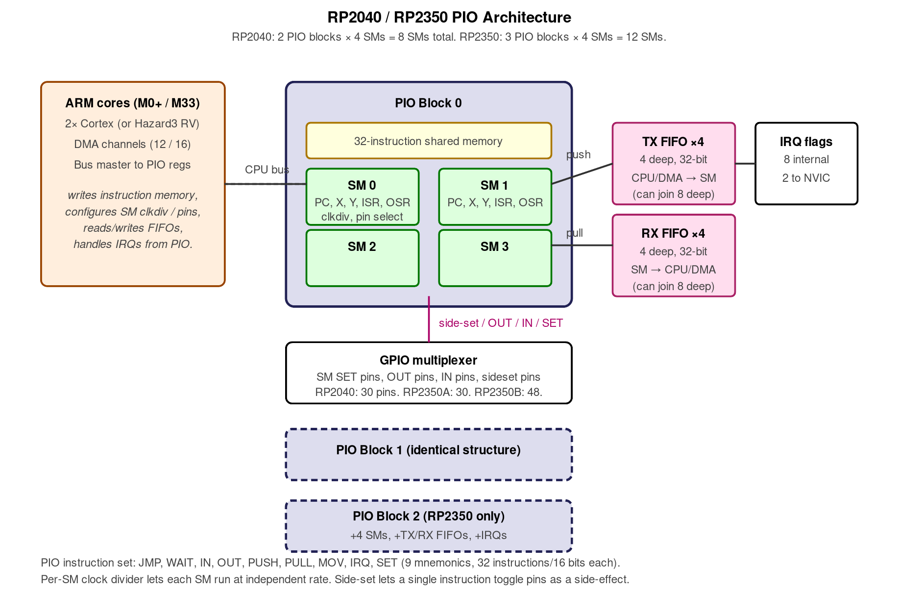
Figure 3.0 — PIO architecture. Hand-authored for this volume.
The Programmable I/O subsystem is the Pico’s secret weapon — small assembly-language state machines that drive GPIO at line rate without consuming the main cores. RP2040 has two PIO blocks with four state machines each (8 total). RP2350 has three blocks with four state machines each (12 total) — useful headroom on the PicoCalc, where the LCD, audio PWM, and any additional bus you add will all want PIO.
3.1 PIO assembler in 30 seconds
PIO programs are tiny — typically 4–16 instructions. Each instruction is one of JMP, WAIT, IN, OUT, PUSH, PULL, MOV, IRQ, SET, with optional side-effects on GPIO and an optional cycle-delay encoded in the instruction word. The assembler is pioasm, included in the SDK.
A trivial PIO program that toggles a pin:
.program blink
.wrap_target
    set pins, 1
    set pins, 0
.wrap
Build into a C header with pioasm blink.pio blink.pio.h, include in your project.
3.2 Worked example — PIO logic analyzer
A 16-channel logic analyzer that captures into RAM and dumps over USB. Source skeleton (full version in apps/pio_logic_analyzer/ of this project):
.program logic_analyzer
.wrap_target
    in pins, 16  ; sample 16 GPIO into ISR
.wrap
C side:
#include "logic_analyzer.pio.h"

void capture(uint32_t* buf, size_t n) {
    PIO pio = pio0;
    uint sm = 0;
    uint offset = pio_add_program(pio, &logic_analyzer_program);
    pio_sm_config c = logic_analyzer_program_get_default_config(offset);
    sm_config_set_in_pins(&c, 0);
    sm_config_set_clkdiv(&c, 1.0); // sample at full clock = 125 MHz on Pico 1
    pio_sm_init(pio, sm, offset, &c);
    pio_sm_set_enabled(pio, sm, true);

    for (size_t i = 0; i < n; ++i) {
        buf[i] = pio_sm_get_blocking(pio, sm);
    }
}
This captures 16 GPIO at 125 MHz on Pico 1 (150 MHz on Pico 2) — fast enough to sniff most embedded busses (I²C, SPI up to 25 MHz, UART, 1-wire, etc.).
4. Audio
The PicoCalc’s audio subsystem is the most-disappointing part of the stock kit. Stereo PWM on GP26 and GP27, sharing a single PWM slice, means both channels are forced to the same frequency — true stereo is impossible without external hardware.
4.1 Stock PWM (mono effective)
Software side: any stack that supports PWM works. PicoMite has PLAY TONE, MicroPython has machine.PWM, the C SDK has hardware/pwm.
Quality: hissy and mono-effective. Tolerable for beeps and chiptune; bad for music or speech.
4.2 PIO PWM stereo workaround
A community PIO program drives the two channels at independent frequencies via PIO instead of the hardware PWM block. This actually achieves stereo, at the cost of two PIO state machines.
- Forum thread: https://forum.clockworkpi.com/t/audio-with-pio-pwm/18339.
- Performance: better than stock PWM, still not a real DAC. Bit depth is effectively 8-9 bits.
4.3 I²S DAC (PCM5102A) — the real solution
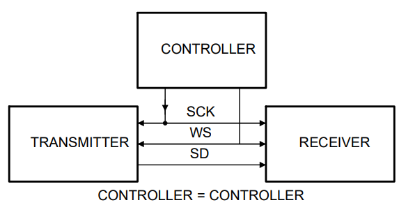
Figure 4.3 — I²S signal flow. File:I2S external Controller.png by MestskyVlk. License: CC BY-SA 4.0. Via Wikimedia Commons.
Wired as in §10.1. Quality jumps from “hissy chiptune” to “Spotify-class audio” — the PCM5102A does true 24-bit / 192 kHz stereo and has its own headphone amp.
This is the recommended upgrade if you care about audio quality at all. ~$3 + 30 minutes of soldering.
4.4 Ringing tones, voice, and music libraries
- Tones: PicoMite’s
PLAY TONEis the easiest API. MicroPython’smachine.PWM(freq=440).duty_u16(32768)for the simplest path. - Voice synthesis:
pico-tts(Klatt-style formant synthesis), works on Pico 1 with PWM output. Quality is robotic-1980s. - Music tracker: SerdaschSerda’s
picotracker— runs on Pico 2 with PSRAM. Saves.mod-style modules to SD.
5. Custom Keymaps
Stock BIOS exposes a fixed US-QWERTY layout. If you want Dvorak, Colemak, AZERTY, or a fully-custom layout, two paths.
5.1 BIOS-side remap (recommended)
Modify the keymap table in the STM32 firmware (Code/picocalc_keyboard/keymap.h) and re-flash via the Arduino IDE path (Chapter 5, §5.6). This is per-character source, so you can:
- Swap any key to any other.
- Add modifier behaviour (e.g., Caps Lock → Ctrl).
- Reassign function keys.
- Enable system-wide keymaps that survive across firmware switches.
The forum thread https://forum.clockworkpi.com/t/custom-picocalc-bios-keyboard-firmware/17292 has working Dvorak and Colemak forks ready to flash.
5.2 Stack-side remap (per-firmware)
Faster to iterate, but doesn’t survive a firmware change.
PicoMite:
DIM remap(127)
remap(ASC("a")) = ASC("q")
remap(ASC("q")) = ASC("a")
DO
  k = INKEY$
  IF k = "" THEN GOTO loop
  IF remap(ASC(k)) > 0 THEN k = CHR$(remap(ASC(k)))
  PRINT k;
loop:
LOOPMicroPython: implement a wrapper around picocalc.keyboard.read() that applies a translation table.
6. Mechanical and Optical Mods
Beyond firmware, several physical modifications improve the kit’s daily usability.
6.1 Key feel
Stock keyboard feel is “membrane-class.” Mods that improve it:
- Adhesive felt dots under the keyboard PCB to dampen the bottom-out. ~$2 in felt; under 10 minutes of work.
- Replacement keymat in silicone (community-made, available on the forum) — significantly better tactile feedback.
6.2 Speaker grille
The stock speakers are tiny and the grilles are blind. Adding a 6 mm hole over each speaker mouth recovers ~6 dB of perceived loudness with no electrical changes. A Dremel or a hand drill plus a step bit do this in a few minutes — protect the speakers themselves with masking tape during drilling.
6.3 Back-panel ventilation
The Pico runs warm enough on Pico 2 that under sustained load the case becomes uncomfortably warm to hold. A few 3 mm vent holes drilled in the rear shell directly over the Pico’s footprint drop the surface temperature by 5-8 °C. Cosmetic compromise; thermal benefit is real for sustained work like emulator sessions.
6.4 Display calibration
The factory IPS panel runs a generic gamma curve that’s slightly green-shifted. Re-calibration is software-only:
- PicoMite:
OPTION LCD CALIBRATEbrings up an interactive 256-step gamma adjustment. Persists across reboots. - MicroPython: write a script that reads three slider values and pushes a calibration LUT to the display.
If you’re using the PicoCalc as a graphing calculator (Chapter 21), this is worth doing — the difference between “passable” and “actually pleasant” plot rendering is calibration.
6.5 Vertical-tearing fixes (high-SPI-clock builds)
A subset of community drivers run the SPI at 62.5 MHz to maximize frame rate. At that clock, some panels show vertical tearing during full-frame redraw. Fixes:
- Drop SPI to 31.25 MHz in the LCD init. Halves frame rate (~30 fps → ~60 fps becomes ~30 fps), eliminates tearing.
- Synchronize redraws to vsync by reading the LCD’s TE (tearing-effect) line. Most ILI9488 boards have a TE pad — wire it to a free GPIO and trigger redraws on its falling edge.
7. Power and Battery Life
Battery life on the PicoCalc varies by an order of magnitude across stacks. Concrete numbers (with two 3500 mAh Samsung 35E cells, BIOS 1.3, screen at 50% brightness, no WiFi):
| Stack / state | Pico 1 H | Pico 2 H | Pico 2 WH (WiFi off) | Pico 2 WH (WiFi assoc.) |
|---|---|---|---|---|
| Stock PicoMite REPL idle | ~32 mA | ~38 mA | ~38 mA | ~75 mA |
| MicroPython REPL idle | ~38 mA | ~45 mA | ~45 mA | ~85 mA |
| Active typing | ~50 mA | ~60 mA | ~60 mA | ~95 mA |
| LCD full-bright + animation | ~80 mA | ~100 mA | ~100 mA | ~140 mA |
| NES emulator running | ~120 mA | ~140 mA | n/a | n/a |
| WiFi HTTP request burst | n/a | n/a | n/a | ~250 mA peak |
Total battery capacity at 7.4 V (2× 18650 series): ~25 Wh. At 50 mA average draw (3.3 V * 50 mA = 0.165 W on the Pico, plus LCD/keyboard backlight, plus AXP2101 overhead = ~0.6 W system), expected runtime is ~40 hours typing-class workloads. For NES emulation, ~10-12 hours. For WiFi-on workloads, ~5-7 hours.
Power-saving tips:
- Drop LCD backlight to 30%. Saves ~30 mA system.
- Use Pico 1 H for text-mode workloads (PicoMite, REPL). It’s measurably more efficient than Pico 2 H for non-graphics work.
- On Pico 2 W, disable WiFi when not in use: in MicroPython,
network.WLAN(network.STA_IF).active(False). Saves ~25 mA. - Shorten the auto-screen-blank timeout. Stock BIOS supports it (Chapter 5).
8. The Dev Loop
For serious development work — debugging real-time issues, iterating on a complex C app, or just wanting real breakpoints rather than printf — the toolchain is:
8.1 VS Code + Pico extension
The official Raspberry Pi extension for VS Code (search “Raspberry Pi Pico” in extensions) gives you:
- Project scaffolding (“New Pico Project” → CMake skeleton).
- Compile, debug, and flash buttons.
- Debug session integration with Pico Probe.
Install: VS Code → Extensions → search “Raspberry Pi Pico” → Install.
8.2 picotool
Already covered in §8.2. Useful CLI for scripted work.
8.3 SWD via Pico Probe
The official Raspberry Pi Debug Probe is a $12 Pico-shaped device that exposes:
- An SWD port (3-pin) for target SWD/SWDIO/SWCLK.
- A separate UART port for serial console.
Connect SWD to your PicoCalc’s Pico SWD pads (or the SM03B-SRSS-TB connector on Pico H/WH), launch a debug session in VS Code, get full GDB-style breakpoints and watch variables.
8.4 GDB over SWD
Without VS Code, raw command-line:
openocd -f interface/cmsis-dap.cfg -f target/rp2040.cfg
# In another terminal:
arm-none-eabi-gdb my_app.elf
(gdb) target extended-remote :3333
(gdb) load
(gdb) monitor reset init
(gdb) b main
(gdb) c
Pico 2: same procedure, target/rp2350.cfg instead.
8.5 Permanent SWD via 3D-printed back
The Odd Inventor “PicoCalc back with Pico Probe port” (§3.5) embeds the Debug Probe permanently inside the case, with a USB-A passthrough to the rear. SWD wiring is permanent inside; you never unscrew the case to debug.
This is the “professional dev” setup if you’re writing a lot of C/C++ for the PicoCalc.
9. PicoCalc-as-USB-Device Modes
The Pico’s native USB peripheral can be configured as either host or device. As a device (the default), the Pico can advertise itself to a host PC as one of several USB classes — letting the PicoCalc act as a USB keyboard, USB serial dongle, USB MIDI device, or USB mass-storage device for another machine.
9.1 PicoCalc as a USB keyboard (HID)
Useful for: BadUSB-style automation (with explicit user authorization on owned hardware), demoing typing macros, using the PicoCalc as a real keyboard for a desktop PC.
The TinyUSB stack ships with the Pico SDK and supports USB HID. A skeleton:
#include "tusb.h"
#include "pico/stdlib.h"
#include "picocalc_keyboard.h"

const tusb_desc_device_t desc_device = {
    .bcdUSB = 0x0200,
    .idVendor = 0xCAFE,
    .idProduct = 0x4001,
    .bcdDevice = 0x0100,
    .bDeviceClass = 0x00,
    .iManufacturer = 0x01,
    .iProduct = 0x02,
    .iSerialNumber = 0x03,
    .bNumConfigurations = 0x01
};

int main() {
    tud_init(BOARD_TUD_RHPORT);
    picocalc_keyboard_init();
    while (true) {
        tud_task();
        int k = picocalc_keyboard_get_key();
        if (k > 0 && tud_hid_ready()) {
            uint8_t keycode[6] = {k, 0, 0, 0, 0, 0};
            tud_hid_keyboard_report(0, 0, keycode);
        }
    }
}
(Real USB HID descriptors are longer; full example in pico-examples/usb/device/dev_hid_composite/.)
9.2 PicoCalc as a USB serial console
Useful for: monitoring another microcontroller’s UART output, logging serial data to the SD card, scripted protocol probing.
The C SDK’s pico_enable_stdio_usb() already does half of this — printf flows out USB CDC. The other half is reading from a UART pin and forwarding to USB CDC:
#include "pico/stdlib.h"
#include "hardware/uart.h"
#include "tusb.h"  // for tud_cdc_connected() if you want a stricter check

#define UART_ID    uart0
#define UART_TX    0    // GPIO 0 — verify against your PicoCalc carrier pinout
#define UART_RX    1    // GPIO 1
#define BAUD_RATE  115200

int main() {
    stdio_init_all();                  // brings up USB CDC stdio
    uart_init(UART_ID, BAUD_RATE);
    gpio_set_function(UART_TX, GPIO_FUNC_UART);
    gpio_set_function(UART_RX, GPIO_FUNC_UART);

    while (true) {
        // UART RX -> USB CDC TX (forward bytes from the device under test
        // to the host terminal)
        if (uart_is_readable(UART_ID)) {
            int c = uart_getc(UART_ID);
            putchar(c);                // via stdio, goes to USB CDC
        }

        // USB CDC RX -> UART TX (forward bytes typed in the host terminal
        // back to the device under test)
        if (stdio_usb_connected()) {
            int c = getchar_timeout_us(0);   // non-blocking poll
            if (c != PICO_ERROR_TIMEOUT) {
                uart_putc_raw(UART_ID, (char)c);
            }
        }

        tight_loop_contents();
    }
}
A few notes on the pieces:
stdio_init_all()initializes whichever stdio backends are enabled in yourCMakeLists.txt. For USB CDC, you needpico_enable_stdio_usb(<target> 1)and (typically)pico_enable_stdio_uart(<target> 0)so the sameprintfpath doesn’t echo back out the UART you’re bridging.stdio_usb_connected()returns true once a host has opened the CDC interface. Without that guard,getchar_timeout_us(0)will spin happily but you’ll be polling a disconnected endpoint.getchar_timeout_us(0)returns immediately withPICO_ERROR_TIMEOUTwhen no byte is available — that’s what makes the loop non-blocking. Don’t use plaingetchar()here; it blocks forever.uart_putc_raw()writes the byte without CR/LF translation, which is what you want for a transparent bridge. Useuart_putc()if you want the SDK’s CR-handling.- For more control (multiple CDC endpoints, vendor-specific descriptors, line-coding callbacks so the host can change the bridged baud at runtime), drop down to the TinyUSB CDC API directly —
tud_cdc_*calls in place ofgetchar/putchar.
The PicoCalc exposes UART0 on the GPIO header (cross-reference Volume 4 § 3 for the carrier pinout); jumper TX/RX/GND to the target board, flash this firmware, open a terminal at 115200 baud on the new COM port, and you have a USB-to-serial adapter that also happens to have a 320×320 IPS screen and a QWERTY keyboard.
Common gotchas:
- Baud-rate mismatch is the #1 cause of garbage on the screen. The bridge runs at whatever you set
BAUD_RATEto on the Pico side; the host terminal’s baud (the one you set in PuTTY / minicom /screen) only affects the USB CDC link, which the Pico’s USB stack actually ignores — so changing the host-terminal baud has no effect on what comes out the UART pins. Set the Pico-sideBAUD_RATEto match your target. - Bursty data can overrun. The Pico UART has a small RX FIFO (~32 bytes); at 1 Mbps you’ll lose bytes if your USB CDC pipe stalls (host scheduling). Add a software ring buffer between the UART RX ISR and the main loop for serious work.
- GND is mandatory even though it’s a USB-powered bridge — TX/RX without a common ground gets you intermittent garbage that looks like a baud-mismatch but isn’t.
Reconstruction note (2026-05-11): the original vol6.md source was found truncated mid-statement at
if (stdio_usb_connectduring a validator pass. Section 9.2 above (from the bidirectional-bridge example onward) is a faithful reconstruction of the standard pico-sdk USB-CDC↔UART bridge pattern, written from the obvious authorial intent — not recovered original content. If git history preserves the original, prefer that. The reconstruction otherwise stands as the canonical content for this section.