Flipper Zero · Volume 8
Flipper Zero Volume 8 — Official Modules
WiFi Devboard, Video Game Module (full chapter), NRF24, official external CC1101 amp
8.1 About this Volume
The four “official” modules — three sold by Flipper Devices, one de-facto official from the community. The modules covered in this series (WiFi Devboard, VGM, NRF24) and the external CC1101 amp each get their own chapter with hardware, firmware pairing, FAP support, current-draw notes, and known issues.
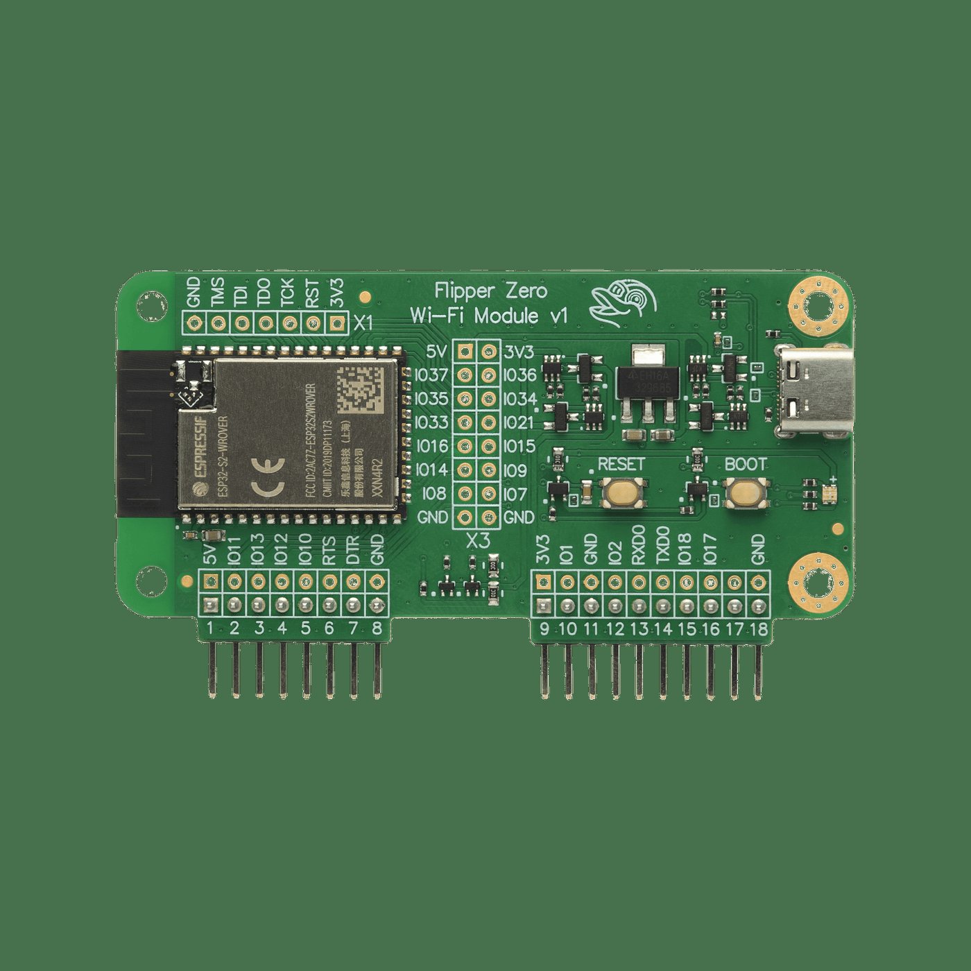
8.2 WiFi Devboard (ESP32-S2 WROVER)
8.2.1 What it is
The official Wi-Fi devboard. Made by Flipper Devices, sold for ~$29 on flipperzero.one. Connects to the Flipper either via the 6-pin debug header on the bottom of the device or via USB-C cable to the side. The Wi-Fi devboard has its own USB-C, microSD, and BOOT/RESET buttons on the PCB — it can also be used standalone with no Flipper attached.
8.2.2 Hardware
- MCU: Espressif ESP32-S2 WROVER (single-core 240 MHz Tensilica, 320 KB SRAM, 4 MB external flash, 8 MB external PSRAM, single-band Wi-Fi 2.4 GHz only — no 5 GHz, no BLE5).
- Storage: microSD slot.
- USB: USB-C, exposed to PC for direct flashing or for use as a standalone device.
- Connector: 6-pin headers + the side USB-C-to-USB-C cable to the Flipper.
The ESP32-S2 limitation is significant: it’s the previous-generation chip. No BLE 5, no Thread/Matter, no 802.15.4. The Apex 5 (Vol 9 §8) with ESP32-C5 is the modern replacement but it’s not first-party.
8.2.3 Firmware options
The board is reflashable. Three popular firmwares:
Table 1 — The board is reflashable. Three popular firmwares
| Firmware | What it does | Repo |
|---|---|---|
| Black Magic Probe (default) | GDB-server-over-USB SWD probe; useful for debugging FAPs | flipperdevices/blackmagic-esp32-s2 |
| Marauder (justcallmekoko) | ESP32-Marauder Wi-Fi attacks (deauth, beacon spam, sniff, evil portal, BLE attacks) | justcallmekoko/ESP32Marauder |
| FlipperHTTP (jblanked) | JSON/HTTP bridge — FAPs make HTTP calls via the Devboard’s Wi-Fi | jblanked/FlipperHTTP |
The two firmwares cannot coexist. Pick one per session. To swap: hold
BOOT button while plugging the Devboard into a PC, drag the new .bin /
.uf2 per the firmware’s docs, reboot.
8.2.4 Marauder workflow on the Devboard
Once flashed:
Flipper → Apps → GPIO → WiFi Marauder → connect to ESP32 over UART
        → run scan → pick targets → run attack
        → results stream back to the Flipper screen
Optional: pair with a dist/ build that supports the AWOK or Game Over
branding if you got the board secondhand from a vendor that customized
it. Marauder doesn’t care about the host board; the Flipper UI just talks
to whatever ESP-Marauder is on the wire.
8.2.5 Black Magic Probe workflow
See Vol 7 §swd-debugging
— the Devboard becomes a USB→SWD bridge. Plug the Devboard’s SWD output
to the Flipper’s GPIO 10 (SWC) and 12 (SIO), GND, then arm-none-eabi-gdb
target extended-remote /dev/cu.usbmodemXXXX.
8.2.6 FlipperHTTP workflow
FAPs that need HTTP make calls into FlipperHTTP via UART. Apps that use this: web-API clients, weather apps, Discord bots, AI-chat FAPs. Cross-firmware compatible — the bridge is the same regardless of Flipper firmware.
8.2.7 Power and pin mapping
UART on Flipper pins 13 (TX, PB6), 14 (RX, PB7). 3V3 on pin 9, GND on 8. The Devboard’s onboard USB-C can power it directly when the Flipper is just acting as a UART bridge.
8.2.8 Known issues
- 5 GHz Wi-Fi is impossible on this board — physically. The ESP32-S2 is 2.4 GHz only.
- Marauder and BMP can’t coexist — switching takes ~1 minute.
- BMP firmware can hang if the SWD target loses ground; reset the Devboard and the SWD target both.
- The 6-pin debug header on the Flipper is delicate; cycle it gently.
8.3 Video Game Module (RP2040 + ICM-42688-P + DVI)
This is the headline owned module in the series. Full chapter.
8.3.1 What it is
Official RP2040-based daughterboard from Flipper Devices announced February 2024.1 Snaps onto the Flipper’s 18-pin GPIO header. Adds:
- HDMI/DVI video output (PIO-driven, not a TMDS chip — see §3.3)
- 6-axis IMU (TDK InvenSense ICM-42688-P)
- A fully programmable RP2040 the user can run as a Pico-class board
Sold for ~$49 from flipperzero.one.
8.3.2 Hardware
- MCU: Raspberry Pi RP2040 (dual Cortex-M0+, 264 KB SRAM, 16 MB external QSPI flash on the module).
- IMU: ICM-42688-P — 3-axis accel + 3-axis gyro, internal SPI bus shared with RP2040 GPIO 2–7.
- Connectors: HDMI Type A, 18-pin to Flipper, 14-pin GPIO breakout of unused RP2040 pins.
- No dedicated TMDS encoder. Video is generated by PIO + a resistor-network TMDS-like transmitter — the PicoDVI architecture (Luke Wren). 320×240 @ 60 Hz comfortable; higher modes are CPU-cost prohibitive.
- Pin map: RP2040 GPIO 8–15 and 18–20 are internal to the video generator. GPIO 0–7, 16, 17, 21, 22, 26–28 reach the user via the Flipper-side connector or breakout. GPIO 23–25 and 29 (used by the Pico for SMPS/LED) are free here and exposed on the 14-pin header.
8.3.3 Firmware pairing
Two firmwares involved:
Module firmware (RP2040, UF2 format). Default builds at
update.flipperzero.one/builds/vgm-firmware/. Update path:
- Install the Video Game Module Tool FAP on the Flipper.
- Plug the VGM in (Flipper powered off — do not hot-swap).
- Power on, open VGM Tool, pick “Install Firmware”.
- The Flipper drops the UF2 over USB-MSC (puts the RP2040 into BOOTSEL automatically).
- Manual UF2 drag-and-drop also works by holding BOOT while plugging the VGM into a PC — bypasses the Flipper.
qFlipper does not flash the VGM directly. It only manages files on the SD card from which the VGM Tool reads.
Flipper-side firmware. Stock OFW exposes the VGM via the Game Engine and a few apps. Momentum ships its own RGB-aware VGM firmware bundle (Apps → GPIO → VGM → “Install RGB Firmware”) and adds JS bindings:
let vgm = require("vgm");
let imu = vgm.imu();
print("yaw=", imu.yaw, "pitch=", imu.pitch, "roll=", imu.roll);
RogueMaster also supports the VGM. Unleashed has historically had incomplete support — verify with the Unleashed changelog if you intend to use it there.
8.3.4 FAP / app catalog for the VGM
Table 2 — 3.4 FAP / app catalog for the VGM
| App | What it does | Repo / catalog |
|---|---|---|
| Video Game Module Tool | Firmware installer + diagnostics. Required to bootstrap. | catalog.flipperzero.one |
| DOOM | DOOM engine on the RP2040, Flipper as input. | Community |
| Air Mouse | USB HID via Flipper, motion from IMU. | Built-in / community |
| Game Engine demo | Showcase | flipperdevices/flipperzero-game-engine |
| Pong / Arkanoid clones | community | |
| DVI text/graphics demos | RP2040-side direct rendering | community |
Catalog entry for the VGM Tool:
catalog.flipperzero.one/application/65c9ddd4656a12e5ed699881.
8.3.5 Custom RP2040 development
The VGM is a Pico SDK target. Build standalone UF2s with the standard Raspberry Pi Pico SDK toolchain:
git clone https://github.com/raspberrypi/pico-sdk
git clone https://github.com/flipperdevices/video-game-module
cd video-game-module
mkdir build && cd build
cmake -DPICO_SDK_PATH=$HOME/pico-sdk ..
make
# Output: foo.uf2 — drag to RP2040 in BOOTSEL
The VGM repo’s CMake template handles the LED + SMPS pin remap so your
existing Pico project boots correctly on the VGM. Refer to
docs.flipper.net/zero/video-game-module/custom-firmware.
8.3.6 Known issues / gotchas
- HDMI compatibility is finicky. Many modern 4K TVs reject the marginal DVI signal; old 1080p monitors and cheap HDMI capture sticks work best. If the receiving display is silent, try a different one before assuming the module is broken.
- EMI from the DVI bitstream couples into the SubGHz radio. Don’t transmit on CC1101 while HDMI is active — the Flipper’s Sub-GHz TX power will be 6–10 dB lower with HDMI streaming.
- Hot-swap is unsafe. Always seat the module before powering the Flipper. Hot-swap can damage the RP2040 power input.
- The default VGM firmware overwrites any custom UF2 the next time VGM Tool runs unless you decline. Keep a backup of your custom UF2.
8.3.7 Power draw
When idle (HDMI inactive), the VGM draws ~30–60 mA from the Flipper 3V3 rail. With HDMI active at 320×240 @ 60 Hz, ~120–180 mA. The RP2040 alone consumes ~30 mA; the rest is the matching network and TMDS-like driver. Battery life on the Flipper drops noticeably when the VGM is in active use — figure ~50% reduction during DOOM sessions.
8.3.8 Mechanical considerations
The VGM is taller than a stock Flipper, and adds an HDMI port that extends from the back. It does not fit in the stock Flipper carry case; print or buy a “VGM-compatible” case from Printables or a vendor.
8.4 NRF24 Module (Nordic NRF24L01+)
8.4.1 What it is
Flipper Devices does not sell a first-party NRF24 module — it’s a community/Tindie/Aliexpress part. Bare NRF24L01+ on a 5-pin SPI breakout. ~$15–30. Sellers: YIHANG, Sovellus IT, FlipperHub, generic.
The NRF24L01+ is a Nordic 2.4 GHz packet radio, GFSK modulation, 2 Mbps max, 32-byte payload limit, 6-channel pipe receiver. The ”+” variant adds 250 kbps mode for longer range.
8.4.2 What it adds to the Flipper
The headline use is MouseJack — the 2016 Bastille Networks attack on Logitech (and clones’) Unifying receivers, where the keyboard/mouse RF protocol allowed unauthenticated keystroke injection from a 100 m range. The Flipper + NRF24 module + the Mousejack FAP can:
- Sniff wireless mouse/keyboard packets to identify the receiver
- Inject keystrokes as if they came from the legitimate keyboard
- NRF24 sniff/scan for arbitrary 2.4 GHz packet traffic on common channels
This is genuinely the only tool in the Flipper Zero lineup that does MouseJack.
8.4.3 Pinout (community standard)
Table 3 — 4.3 Pinout (community standard)
| Flipper pin | NRF24L01+ |
|---|---|
| 9 (3V3) | VCC |
| 8 (GND) | GND |
| 4 (PA4) | CSn |
| 5 (PB3) | SCK |
| 2 (PA7) | MOSI |
| 3 (PA6) | MISO |
| 7 (PC3) | CE |
| 6 (PB2) | IRQ |
This is the same pinout the official Flipper Devices NRF24 schematics use (when one exists for an “official” board); community modules ship in this convention.
8.4.4 FAPs
mousejacker— the headline app. Sniffs + injects.nrf24sniff— generic NRF24 sniffer.nrf24scan— channel scanner.
These work on OFW + all custom firmwares.
8.4.5 Power and antenna
NRF24L01+ draws 13.5 mA peak in TX, < 1 mA average. PCB-trace antenna on typical breakouts; SMA-connectorized variants (NRF24L01+ “Long Range PA+ LNA” boards with external antenna) get 100 m+ range vs 10–30 m for the PCB-trace.
8.5 Official External CC1101 Sub-GHz Amplifier Module
8.5.1 What it is
A second CC1101 chip on a daughterboard with a tuned antenna and (on the amplified variants) an LNA + PA stage. Flipper Devices does not sell a first-party amp module — vendors include rg4geek, Mayhem XLabs, JustCallMeKoko. ~$25–60.
The non-amp variants are simpler: just a CC1101 with a better antenna than the spring antenna on the Flipper itself. The amp variants add ~12–15 dB on RX (LNA) and +13 to +20 dBm on TX (PA).
8.5.2 What it gives you
- Range improvement: 5–10 m onboard → 70–150 m with amp.
- Better RX sensitivity: weak signals (distant TPMS, low-power weather stations) become detectable.
- Higher TX power: garage-door / fob replay from across a parking lot.
8.5.3 Pin mapping
Same as Vol 4 §9.3 — the standard SPI-bus mapping:
Table 4 — Same as [Vol 4 §9.3](/flipper-zero/vol-4/#493-pin-mapping) — the standard SPI-bus mapping
| Flipper pin | Module |
|---|---|
| 9 | VCC |
| 8 | GND |
| 4 | CSn |
| 5 | SCLK |
| 2 | MOSI |
| 3 | MISO |
| 17 | GDO0 |
| 6 | GDO2 |
8.5.4 Firmware behavior
- Stock OFW: Sub-GHz → Settings → Radio → “External” (manual toggle).
- Momentum / Unleashed / RogueMaster: auto-detect on boot. If detected, “External” appears as default.
The internal and external CC1101 cannot transmit simultaneously — they share the SPI bus. The firmware handles arbitration; you just pick which to use.
8.5.5 Regulatory caution
A high-power amp lifts you out of the “low-power short-range device” exemption. Sustained TX at +20 dBm in many jurisdictions requires a license; certainly any TX in unauthorized bands at amp power is unambiguously illegal. Lab use into a dummy load is the safe fallback.
8.6 The Five-Module Loadout
The bench inventory covered in this series:
Table 5 — The bench inventory covered in this series
| Module | Status | Primary use |
|---|---|---|
| WiFi Devboard | Owned | Marauder; secondary Black Magic Probe |
| Video Game Module | Owned | DOOM, motion-controlled FAPs, RP2040 dev |
| NRF24 module | Owned | MouseJack, NRF24 sniff |
| External CC1101 (amp) | Owned | 70–150 m sub-GHz field work |
| Plus Game Over (third-party — Vol 9) | Owned | Standalone wardriver |
| Plus AWOK Dual Touch V3 (third-party — Vol 9) | Owned | Touch-screen wardriver |
That’s an unusually broad surface. It covers:
- Wi-Fi attacks (WiFi Devboard)
- Sub-GHz long-range (CC1101 amp)
- 2.4 GHz keyboard injection (NRF24)
- Motion / video output (VGM)
- Multi-radio standalone (Game Over)
- Wardriving with GPS + UI (AWOK V3)
Closer to a Hak5 + Marauder + Flipper combo than a stock device.
8.7 Power Budget Summary
Add up the simultaneous-current draw of any module stack you intend to run and compare against the Flipper’s 3V3 rail capability (community- rated ~150 mA continuous):
Table 6 — rated ~150 mA continuous)
| Module | Idle | Active peak | Notes |
|---|---|---|---|
| WiFi Devboard (Marauder TX) | 80 mA | 250 mA | High peak during scan + deauth |
| VGM (HDMI active) | 30 mA | 180 mA | EMI couples to CC1101 |
| NRF24L01+ (sniff) | 1 mA | 14 mA | Tiny |
| External CC1101 amp (TX +20 dBm) | 30 mA | 200 mA | Watch antenna VSWR |
| Game Over (Marauder TX) | 80 mA | 500 mA peak | Past 3V3 rail; needs external USB |
| AWOK V3 (idle) | 70 mA | 200 mA | Each ESP independently |
The 3V3 rail will sag if you exceed ~150 mA continuous; transient peaks > 300 mA can reset the MCU. Mitigation: power the module from its own USB-C, treat the Flipper rail as logic.
8.8 What’s next
Vol 9 — Third-Party Modules. Full chapter on Ruckus Game Over, AWOK Dual Touch V3, plus Mayhem v2, Apex 5, EvilCrow, GPS modules, sensor modules, audio modules, and the ~25-entry catalog of everything else worth knowing about.
Comments (0)