Chameleon Ultra · Volume 7
Chameleon Ultra — Slot Management and Card Organization
The 8+8 slot architecture; naming, ordering, and exporting slots; managing a multi-credential field inventory
7.1 The 8+8 slot architecture in practice
The Chameleon Ultra implements a dual-bank slot model: eight HF slots (ISO 14443A / 13.56 MHz) and eight LF slots (125 kHz), each managed independently. This is not an 8-slot device where HF and LF share capacity — the two banks are orthogonal, so a device carrying 8 loaded HF credentials still has all 8 LF slot positions available. Total emulation credential capacity is 16 distinct protocol-level configurations in a single sub-credit-card device.
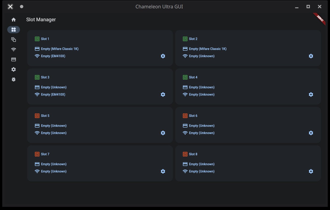
A “slot” in the Chameleon Ultra is a compound record. Each of the 8 slot positions can carry an HF card configuration (card type, UID, ATQA, SAK, and full memory dump), an LF card configuration (protocol family and credential ID), both simultaneously, or neither. The distinction matters operationally: an HF and an LF credential loaded into slot 3 are presented together when slot 3 is active — an HF reader interrogates the HF side, and an LF reader interrogates the LF side, without requiring the operator to manage two separate slot indices.
7.1.1 HF and LF banks are independent
The HF and LF banks share a slot numbering (1–8) but do not share storage or capacity. Assigning all 8 HF slots to MIFARE Classic 1K emulations does not consume any LF slot capacity. An engagement that requires 8 distinct HF credentials and 6 distinct LF credentials can be provisioned without slot conflict — slots 1–8 each carry an HF card, and slots 1–6 additionally carry an LF card, with slots 7 and 8 having their LF sides empty.
This independence extends to the enable state. Firmware v2.0.0 (RRG CHANGELOG, 2023-09-26) introduced separate enabled_hf and enabled_lf fields per slot, replacing the earlier single per-slot enable flag. A slot’s HF side can be enabled while its LF side is disabled, and vice versa. Disabling one frequency on a slot does not alter the configuration stored for that band — it instructs the device not to respond on that band’s frequency for that slot position, while preserving the stored credential for later re-enablement.
7.1.2 Active slot concept
Of the eight slot positions, one is the “active” slot at any given time — the slot the device presents to an interrogating reader when powered. The active slot index is shared across both bands: when slot 3 is active, the HF side of slot 3 is what the HF coil face responds with, and the LF side of slot 3 is what the LF coil face responds with. There is no separate HF-active and LF-active index; a single slot change advances both bands simultaneously.
For an operator who has loaded an HF credential and its corresponding LF credential for the same physical door into slot 2 — because the door reader interrogates both 13.56 MHz and 125 kHz — a single button press to slot 2 presents both credentials, synchronizing the presentation without requiring separate HF-slot and LF-slot management.
7.1.3 Capacity planning for an engagement
Sixteen total slot configurations (8 HF + 8 LF) is sufficient for the overwhelming majority of physical-pentest engagements. Most single-building assessments involve three or fewer distinct access-control credential types; a multi-building campus engagement might require 6–8 HF types and 3–4 LF types — well within the slot budget. Practical loadout planning:
- Slot 1: Primary HF target credential (typically MIFARE Classic 1K, the most common enterprise access card). If the same access point uses a dual-band reader, configure both HF and LF sides of slot 1.
- Slots 2–4: Secondary HF credentials (secondary buildings, parking garages, stairwell readers that may use a different card type or different sector-key set).
- Slots 5–7: LF-only credentials (HID Prox fobs, EM4100 site codes) where no corresponding HF card is needed. Leave the HF sides of these slots empty.
- Slot 8: Reserved for opportunistic in-field capture via the button long-press Copy function (Vol 2 §6.1 — holding either button when a compatible field is present loads the detected card’s UID into the current active slot). Pre-positioning slot 8 as the designated capture slot avoids overwriting an operational credential during a field grab.
Most field engagements involve fewer than 8 distinct credentials per band. Having unused slot positions is not a resource waste — empty slots do not degrade emulation performance on occupied slots.
7.2 HF slot inventory — configuring and naming 8 HF slots
The HF side of each slot requires two configuration steps before emulation: setting the card type and initializing the slot data structure. Both are handled through the hw slot command tree in the CLI or through the Slot Manager in ChameleonUltraGUI.
7.2.1 Per-slot card type configuration
hw slot type sets the protocol type metadata for a slot; hw slot init populates the slot’s emulation memory with a default data structure for that type. Both commands take a slot number (-s 1 through -s 8) and a type identifier from the firmware’s TagSpecificType enum.
Table 1 — 2.1 Per-slot card type configuration
| Card type | CLI type identifier | Emulation memory size |
|---|---|---|
| MIFARE Classic 1K | MIFARE_1024 | 1024 bytes (16 sectors × 4 blocks × 16 bytes) |
| MIFARE Classic 4K | MIFARE_4096 | 4096 bytes (40 sectors) |
| MIFARE Ultralight | MIFARE_ULTRALIGHT | 64 bytes |
For a complete list of type identifiers (DESFire variants, NTAG subtypes, and additional HF protocol types added in successive firmware releases), run hw slot type --help on a connected device or consult the RRG CLI reference at github.com/RfidResearchGroup/ChameleonUltra/wiki/cli. The exact identifier string must match the firmware’s enum; the CLI rejects unrecognized type strings.
CLI workflow — loading a MIFARE Classic 1K dump into HF slot 2:
hw slot type -s 2 -t MIFARE_1024
hw slot init -s 2 -t MIFARE_1024
hf mf eload -s 2 -f lobby_badge.bin -t bin
hw slot enable -s 2 --hf
hw slot change -s 2
hw slot type sets the type metadata. hw slot init populates emulation memory with a default structure for MIFARE_1024 — zeroed sector data, placeholder UID DEADBEEF, and default ATQA/SAK matching the type. hf mf eload overwrites the initialized data with the captured dump. hw slot enable -s 2 --hf activates HF emulation for slot 2. hw slot change -s 2 makes slot 2 the active slot. This sequence is the verified pattern from Vol 6 §7.1 and is the canonical CLI path for HF slot loading.
GUI workflow (ChameleonUltraGUI):
The Slot Manager presents 8 cards, one per slot. Each card displays the slot number, an RFID icon indicating enabled/disabled state (green = enabled, red = disabled), and the loaded card name and type for the HF and LF sides. To configure an HF slot:
- Tap the target slot card to open its detail view.
- On the HF section (shown with a credit-card icon), select the card type from the dropdown.
- To load an existing dump, tap Import. A CUGUI JSON file imports immediately with card type auto-populated from the JSON metadata. A raw
.binfile triggers a card-type confirmation prompt before writing. - Enable the HF side by toggling the HF enable switch. The slot card’s RFID icon turns green when a valid card type is configured and the HF side is enabled.
7.2.2 Naming HF slots
Each slot’s HF side and LF side carry independent nicknames, stored in flash as UTF-8 strings up to 32 bytes (per the RRG protocol specification, SET_SLOT_TAG_NICK / GET_SLOT_TAG_NICK commands; maximum 32 bytes, no null terminator). The 32-byte limit accommodates approximately 32 ASCII characters or 8–10 Chinese/Japanese/Korean characters (UTF-8 encodes CJK codepoints in 3 bytes each). Nickname encoding was migrated from GBK to UTF-8 in firmware v2.0.0 (RRG CHANGELOG); v1.x devices stored GBK-encoded nicknames, and any nicknames set under v2.0.0+ will render as garbled text if viewed on a v1.x device.
CLI nickname commands (v2.1.0+ syntax; confirmed from RRG Issue #164 and CHANGELOG v2.1.0 CLI rework):
hw slot nick -s 2 --hf -n "Lobby badge MC1K"   # set HF nickname for slot 2
hw slot nick -s 2 --hf                           # display current HF nickname
hw slot nick -s 2 --hf -d                        # delete HF nickname
The --hf flag targets the HF band’s nickname; --lf targets the LF band. Setting an HF nickname does not affect the LF nickname for the same slot — they are stored independently using the sense_type field of SET_SLOT_TAG_NICK. If no nickname has been set for a slot-band combination, GET_SLOT_TAG_NICK returns STATUS_FLASH_READ_FAIL — not an error condition, but the firmware’s way of indicating the nickname field is empty. Confirm exact flag behavior with hw slot nick --help on a connected device if running a firmware build older than v2.1.0.
Nicknames appear in hw slot list output and in hw slot list --short (the compact form was enhanced in v2.1.0 to display names alongside HF anticollision data and LF IDs; RRG CHANGELOG: “Changed hw slot list to display LF ID & HF anticol data, and names in the —short version too”). In ChameleonUltraGUI, the slot nickname appears as the card name label on the slot card in the Slot Manager grid. Nicknames set via CLI are visible in the GUI, and nicknames set in the GUI are written back to the device via SET_SLOT_TAG_NICK.
Recommended naming convention for pentest use: [Location] [card type] — for example "Lobby badge MC1K", "Parking HID26", "Lab DESFire". Keeping names under 20 ASCII characters leaves comfortable headroom within the 32-byte budget.
7.2.3 Reviewing the HF slot inventory
hw slot list is the primary inventory command. As of firmware v2.1.0, its output includes each slot’s HF card type, HF anticollision data (UID, ATQA, SAK), LF credential identifier, and both HF and LF nicknames. The --short flag produces a compact summary suitable for quick field verification:
hw slot list         # full output per slot
hw slot list --short # compact: type, nick, HF anticol data, LF ID
In ChameleonUltraGUI, the Slot Manager grid provides the same overview visually: each of the 8 slot cards shows the loaded HF card name (from the slot’s HF nickname), the card type, and the enable state. The HF and LF sides are visually distinguished within each card by different icons.
7.3 LF slot inventory — configuring and naming 8 LF slots
The LF side of a slot follows the same configuration structure as the HF side. hw slot type, hw slot init, hw slot enable, and hw slot nick all accept --lf to target the LF configuration. The cardinal difference is the type identifier set: LF types are protocol families rather than memory card geometries.
Table 2 — 3. LF slot inventory — configuring and naming 8 LF slots
| Protocol family | CLI type identifier | Notes |
|---|---|---|
| EM4100 / EM4102 | EM410X | 40-bit read-only UID; most common deployed 125 kHz format (confirmed Vol 6 §3.3) |
| HID Prox | — | Exact firmware type identifier — confirm with hw slot type --help |
| Indala | — | Exact firmware type identifier — confirm with hw slot type --help |
| T5577 | — | T5577 is a writable tag configured to emulate EM/HID/Indala; check firmware docs for the emulation type identifier |
The EM410X identifier is the only LF type string confirmed across Vol 6 and the RRG CLI wiki. For other LF protocol families, the firmware’s TagSpecificType enum defines the identifier; consult the RRG CLI reference or hw slot type --help rather than inferring the string from the protocol name.
7.3.1 Per-slot LF protocol configuration
CLI workflow — loading an EM4100 credential into LF slot 3:
hw slot type -s 3 -t EM410X
hw slot init -s 3 -t EM410X
lf em 410x econfig -s 3 --id DEADBEEF88
hw slot enable -s 3 --lf
This is the verified pattern from Vol 6 §3.3 applied to an LF-only slot (slot 3’s HF side is left unconfigured here). For other LF protocol families, substitute the appropriate type identifier and the corresponding lf <family> econfig command. The exact econfig syntax per protocol is confirmed in the RRG CLI reference; do not infer flag names for unfamiliar families.
A slot can carry both HF and LF credentials simultaneously. If slot 3 already has an HF card configured, adding an LF credential does not displace the HF side:
hw slot type -s 3 -t EM410X       # sets LF type (HF type is unaffected)
hw slot init -s 3 -t EM410X       # initializes LF data (HF data is unaffected)
lf em 410x econfig -s 3 --id <ID> # writes LF credential
hw slot enable -s 3 --lf          # enables LF (HF enable state is unaffected)
GUI workflow: In ChameleonUltraGUI’s Slot Manager, the LF side of each slot card is shown with a distinct icon (per the GUI wiki: a Wi-Fi-style icon separate from the HF credit-card icon). Tap the LF section to select the LF protocol type from a dropdown and enter the credential value. The workflow mirrors HF configuration in structure.
7.3.2 Naming LF slots
LF nicknames are stored independently from HF nicknames via the same SET_SLOT_TAG_NICK protocol command, using the LF sense type:
hw slot nick -s 3 --lf -n "Parking EM4100"    # set LF nickname for slot 3
hw slot nick -s 3 --lf                          # display current LF nickname
hw slot nick -s 3 --lf -d                       # delete LF nickname
The same 32-byte UTF-8 limit applies. A single slot can therefore carry two independent nicknames — one for its HF credential and one for its LF credential. Setting or deleting one does not affect the other. In the GUI, both the HF and LF card names within a slot card reflect their respective nicknames.
7.3.3 Reviewing the LF slot inventory
hw slot list includes LF credential data alongside HF data in the same output. The v2.1.0 CHANGELOG entry “Changed hw slot list to display LF ID & HF anticol data, and names in the —short version too” confirms that hw slot list --short shows LF IDs and LF nicknames alongside HF anticollision data for all 8 slots in one compact view. This makes hw slot list --short the fastest CLI command for a full loadout overview before entering the field.
7.4 Switching between slots — button behavior and BLE app interface
The Chameleon Ultra exposes two slot-switching mechanisms: the physical buttons on the device (used when no BLE client is connected or as a quick field switch without opening the app) and the ChameleonUltraGUI Slot Manager (direct selection by slot number from the grid).
7.4.1 Button-only slot cycling
Per the current RRG firmware (confirmed in Vol 2 §6.1, which documents the authoritative button table):
- Button A short press: select previous slot (cycle down; slot 1 wraps to slot 8)
- Button B short press: select next slot (cycle up; slot 8 wraps to slot 1)
The cycle is across the full 8-slot space. There is no separate HF-slot-cycle and LF-slot-cycle; the active slot index is shared between both bands. One button press advances the index for both bands simultaneously. A slot configured with only an HF card and no LF card can still be the active slot — the LF side simply presents nothing when interrogated.
The LED strip updates immediately on each button press: the previously active slot’s LED extinguishes and the newly active slot’s LED illuminates in the color corresponding to its content (§7.1). For a loadout where each slot carries a different credential type, the color change on button press confirms the transition without requiring the BLE app.
Wake note: the device enters low-power sleep after approximately five seconds of inactivity, during which the LED strip powers down (Vol 2 §6.2). The first button press wakes the device; the second press changes the slot. When cycling slots rapidly from sleep, account for the wake press not advancing the slot.
The button long-press actions (holding either button when a compatible RF field is present) are a separate function — opportunistic UID capture into the current active slot (Vol 2 §6.1). Long-press does not cycle slots; it loads a detected card into whichever slot is currently active.
7.4.2 BLE app direct slot selection
ChameleonUltraGUI’s Slot Manager provides direct slot selection without sequential cycling. Tapping any slot card in the 8-card grid makes that slot active immediately — the equivalent of hw slot change -s <n> over USB-C but without requiring a cable. The GUI updates the active-slot indicator (a red circle on the active slot per the GUI wiki) to reflect the change, and the LED strip on the device updates simultaneously.
For multi-slot field sessions where a phone is available, this is the preferred selection method: the operator can jump from slot 1 to slot 7 without pressing through slots 2–6, and the slot card displays the nickname label confirming the correct credential before the device is presented to a reader.
The CLI equivalent for USB-C sessions:
hw slot change -s 77.4.3 Slot switching without a phone
In environments where phone use is restricted — secure areas, RF-restricted zones, covert engagements — the button-only workflow is the sole local control surface. Practical discipline:
- Pre-plan slot arrangement so the desired credentials are reachable in a known number of presses from the initial position. A sequential loadout (primary credential in slot 1, secondary in slot 2, etc.) minimizes the maximum press count to reach any slot.
- Track the current active slot by counting the lit LED position: slot 1 = leftmost LED, slot 8 = rightmost. At 8 slots and a horizontal LED strip, the position is identifiable by inspection.
- Note the LED color to confirm content type (§7.1): green = HF only, blue = LF only, red = both. If the lit LED is the correct position but the wrong color, the slot’s credential type does not match the expected loadout — verify via
hw slot listover USB-C before proceeding.
The device has no display. LED position-counting is the only on-device slot-identity confirmation without a BLE or USB connection. This is a deliberate tradeoff in the Chameleon Ultra’s form factor (Vol 2 §6 — the design philosophy is that the phone is the real control surface; the buttons and LEDs are a minimal fallback).
7.5 Exporting and importing slot data — dump files, formats
Vol 6 §6 covers the dump file format table (CUGUI JSON / raw binary / MCT) and the hf mf esave / hf mf eload CLI commands in operational depth. This section adds the credential-library management perspective and the import/export flow from ChameleonUltraGUI’s Saved Cards section.
7.5.1 Exporting a slot dump
CLI:
hf mf esave -s 2 -f lobby_badge.bin -t binThis exports the emulation memory of HF slot 2 as a raw binary dump (verified in Vol 6 §6.2). The -t flag accepts bin (raw flat binary) or hex; bin is the cross-tool interchange format compatible with Proxmark3’s hf mf eload and the iCopy-X import interface. Omitting -s exports the currently active slot.
GUI:
In ChameleonUltraGUI, card dumps are managed in the Saved Cards section (distinct from the Slot Manager; the Saved Cards section is the host-side card library). Each saved card entry has a quick-action export button. The export dialog offers CUGUI JSON or .bin format. Exported files are written to the phone’s document store (Android: Documents/ChameleonUltraGUI/; iOS: Files app under the ChameleonUltraGUI folder) or to a user-selected path on desktop installs. Cards are auto-saved to the Saved Cards library at the end of a read/recovery workflow, or can be saved manually from the slot context menu in the Slot Manager.
For LF credentials, export is the raw protocol ID value (e.g., the 40-bit EM4100 ID). The LF credential can be recorded from hw slot list --short output or from the lf econfig display for the slot. There is no binary dump file for LF credentials in the same sense as HF sector data; the LF credential is a protocol ID value that can be noted and re-entered.
7.5.2 Dump file formats and naming
The formats supported by ChameleonUltraGUI for MIFARE Classic HF dumps (confirmed from Vol 6 §6.1 and GUI wiki):
Table 3 — The formats supported by ChameleonUltraGUI for MIFARE Classic HF dumps (confirmed from Vol 6 §6.1 and GUI wiki)
| Format | Extension | Description | Cross-tool compatibility |
|---|---|---|---|
| CUGUI JSON | .json | ChameleonUltraGUI native; includes card type, UID, nickname, and block data as JSON. Imports immediately without type prompting. | CU GUI only |
| Raw binary | .bin | Flat binary: 1024 or 4096 bytes in block order, no header. Proxmark3 hf mf dump produces this format. | Proxmark3, iCopy-X, MCT (partial) |
| MCT | .mct | MIFARE Classic Tool format with +Sector:N headers; hex-encoded sector data. | Android MCT app, MTools |
| EML | .eml | Hex-encoded flat format, accepted by ChameleonUltraGUI import dialog. | EML-compatible tools |
For cross-tool workflows — a Proxmark3 RDV4 dump loaded into the CU, or a CU dump exported to the iCopy-X — the .bin format is the interchange layer (Vol 6 §6.3). For CU-internal credential library management, CUGUI JSON is preferred because it carries card type metadata, eliminating the re-prompting step on import.
For a credential library, a naming convention that includes the engagement, location, card type, and slot number makes the library navigable without opening each file: engagement_YYYYMMDD/slot02_lobby_mc1k.bin, engagement_YYYYMMDD/slot02_lobby_mc1k.json. Keeping both .bin and CUGUI JSON copies of each dump ensures the .bin is available for cross-tool use and the JSON is available for fast re-import into the GUI.
7.5.3 Importing a dump into a slot
CLI:
hw slot type -s 4 -t MIFARE_1024
hw slot init -s 4 -t MIFARE_1024
hf mf eload -s 4 -f captured_card.bin -t bin
hw slot enable -s 4 --hf
The card type must be set before hf mf eload. The hw slot init call allocates the emulation memory structure for the correct card geometry; hf mf eload writes the dump data into that structure. Attempting to load a 1K dump (1024 bytes) into a slot configured for 4K (4096 bytes), or vice versa, produces a sector-structure mismatch — the symptom is emulation failure at readers that authenticate beyond the overlapping sector range. See §8.2 for the full mismatch analysis.
GUI:
In the Slot Manager, tap the target slot, then the HF section, and tap Import. If a CUGUI JSON file is selected, the import is immediate — the GUI sets the card type from the JSON metadata without additional prompting. If a raw .bin file is selected, the GUI prompts for card type confirmation before writing. After import, verify the UID, ATQA, and SAK displayed in the slot card match the original card’s values from the hf 14a scan that produced the dump.
7.5.4 Building a credential library
The Saved Cards library in ChameleonUltraGUI persists on the host device (phone or laptop), not on the Chameleon Ultra hardware. This means the library survives a factory reset of the Ultra hardware, and a new or reset Ultra can be re-loaded from the same library without re-capturing credentials from scratch. For a team of operators sharing a card library, the library can be backed up as a folder of CUGUI JSON and .bin files and re-imported on any ChameleonUltraGUI instance.
A practical library structure organized by engagement:
dumps/
  engagement_YYYYMMDD_sitename/
    slot01_lobby_mc1k.json
    slot01_lobby_mc1k.bin
    slot02_elevator_mc1k.json
    slot02_elevator_mc1k.bin
    slot05_parking_hid26.txt       # LF: just the EM/HID ID value + site code
    slot06_reception_em4100.txt
Keeping the LF credential as a text note (the raw ID value and protocol) alongside the HF dump files completes the per-slot record and enables full slot reconstruction from the library files without the original physical cards.
7.6 Building a pre-engagement slot set
Preparing the Chameleon Ultra before a physical-pentest engagement is a workflow of its own. The goal is a device where every slot is loaded with a tested, verified credential, every slot is labeled, and the operator can navigate to any credential under field conditions without ambiguity.
7.6.1 Pre-engagement checklist
Before entering the field:
- Firmware version: Run
hw version. Confirm the device is on the expected firmware. Note any version-dependent behavior (HardNested requires v2.1.0+, as covered in Vol 4). - Battery charge: No CLI command reports state-of-charge (Vol 2 §7.2 — no fuel gauge). The 4-pulsing-green-LED pattern indicates charging in progress; steady or no LED indicates charge complete. Charge to full before each engagement; the 90 mAh LiPo supports many hours of intermittent field use but should not enter the day at partial charge.
- Slot types confirmed: Run
hw slot listand verify each configured slot shows the expected card type. An “empty” or residual-type slot indicates a credential was not loaded or was not saved correctly. - Slot nicknames set: Run
hw slot list --shortand confirm that every populated slot shows the expected HF and LF nicknames. An unlabeled slot requires the operator to recall what was loaded; a mislabeled slot causes the wrong credential to be presented at the target. - HF and LF enable states verified: Confirm each slot’s HF and LF enables are correctly set. A slot with a loaded MIFARE Classic dump but HF disabled will present nothing to HF readers — a failure that looks like a card-type mismatch but is simply an enable flag.
hw slot listoutput shows enable state per slot. - Emulation tested against a lab reader: See §6.3. This is the step that catches the class of failure (ATQA/SAK mismatch, partial sector dump, LF protocol error) that is invisible in the slot configuration but rejected at the reader.
- BLE app connected and slot grid verified: Open ChameleonUltraGUI over BLE, navigate to the Slot Manager, and confirm the 8-card grid shows expected card names, types, and enable states for all configured positions.
- Saved Cards library has copies of all slot dumps: Verify the GUI’s local card library contains an entry for every slot’s credential, so the device can be reloaded if it is factory-reset, lost, or seized.
7.6.2 Slot assignment strategy
A consistent slot assignment convention reduces cognitive load under field conditions. A recommended convention for multi-target engagements:
- Slot 1: Primary HF credential for the most commonly needed access point. Load both HF and LF sides if the same door is dual-band.
- Slots 2–4: Secondary HF credentials in priority order (secondary buildings, floor-specific readers, elevator credentials). Load corresponding LF sides if applicable.
- Slots 5–7: LF-only credentials (sites that use only 125 kHz readers; fobs captured by EM4100 or HID Prox read). Leave the HF sides empty.
- Slot 8: Reserved. Either empty (for opportunistic field capture via button long-press) or loaded with a “fallback” credential for a primary site in case slot 1’s emulation is rejected at a reader with anti-emulation measures.
For dual-band access points — a reader that interrogates both HF and LF — loading both credentials into the same slot number (e.g., HF side of slot 2 = building B MIFARE Classic, LF side of slot 2 = building B HID Prox backup) keeps them synchronized under a single button press and a single LED position.
7.6.3 Testing before going live
Validate every loaded slot against a known-good lab reader before presenting at the operational target. A lab reader is any reader physically identical or equivalent to the target — a spare reader unit from the same system, a second reader of the same model, or a test access point at a controlled location.
The validation sequence per slot:
- Make the slot active (
hw slot change -s <n>or button cycle or GUI tap). - Field detection confirmation: Present the active slot to the HF or LF face of the lab reader. The white RF LED on the CU edge illuminates when a reader field is detected at the active slot’s frequency — if it does not light, the device is not coupling. Check face orientation (HF coil = main PCB face; LF coil = antenna PCB reverse, per Vol 2 §5).
- Anticollision recognition: Verify the reader responds to the emulated UID/ATQA/SAK for HF slots. A SAK mismatch causes readers with card-type validation to reject at selection. If the reader shows “unknown card” or hangs, re-check the slot’s configured ATQA and SAK against the original
hf 14a scanoutput. - Crypto1 authentication: For MIFARE Classic slots, success is confirmed when the reader grants access (or returns the same outcome as the physical card). Failure here, with the correct UID/ATQA/SAK, indicates a sector key error — re-run key recovery or verify the dump’s sector key map shows no unresolved sectors (Vol 6 §2.5).
- LF credential recognition: For LF slots, the reader should respond immediately. A no-response outcome typically means the LF side is not enabled, the protocol type is mismatched, or the ID value was entered incorrectly.
The class of failures that only manifests at the reader — incorrect SAK, partial dump with missing sector keys, wrong LF protocol — cannot be caught by inspecting the slot configuration alone. A lab test pass per slot is the only pre-engagement verification that catches reader-side rejection before the field session begins.
7.7 RGB LED slot indicators
Vol 2 §6.2 is the authoritative reference for the full LED state table, including charging, DFU, and USB session animations. This section focuses on the LED’s slot-management-relevant behaviors: reading the LED strip to determine active slot identity and content type without opening the BLE app.
The Chameleon Ultra has eight individually addressable RGB LEDs arranged in a horizontal strip, one per slot (slot 1 = leftmost, slot 8 = rightmost). The LED array simultaneously encodes active slot position (which LED is lit), content type (color), and fill status (unlit = empty or disabled slot). For a device with slots 1–3 loaded and slots 4–8 empty, exactly three LEDs are lit — the filled slots.
7.7.1 LED color scheme
Per the current RRG firmware (confirmed in Vol 2 §6.2, sourced from RRG ChameleonUltraDocs/firmware.md):
Table 4 — Per the current RRG firmware (confirmed in Vol 2 §6.2, sourced from RRG ChameleonUltraDocs/firmware.md)
| LED color (idle or field-detected) | Slot content |
|---|---|
| Green | HF (13.56 MHz) card configured and enabled; LF side empty or disabled |
| Blue | LF (125 kHz) card configured and enabled; HF side empty or disabled |
| Red | Both HF and LF cards configured and enabled in the same slot |
| Off | Slot is empty (no HF or LF configuration), or both HF and LF are disabled |
These colors reflect the configured content of a slot. For a typical engagement loadout:
- Slots with MIFARE Classic HF credentials only → green LEDs
- Slots with EM4100 or HID Prox LF credentials only → blue LEDs
- Slots carrying both an HF and an LF credential for the same access point → red LEDs
- Empty or reserved slots → no LED
Reading the LED strip from left to right provides a rapid visual inventory of the entire loadout: green/blue/red/dark/dark/dark/dark/dark is immediately interpretable as “three slots loaded, slot colors confirm HF-only / LF-only / dual-band respectively, five slots empty.” This is the only real-time inventory view available without a BLE or USB connection.
Note that the white RF LED on the device edge (separate from the slot LED strip) illuminates when any reader field is detected at the active slot’s frequency — this is independent of slot content and fires on field presence regardless of whether the active slot has a card configured.
7.7.2 Interpreting LED during slot switching
During button-press slot cycling, the LED strip updates immediately on each press:
- The previously active slot’s LED extinguishes.
- The newly active slot’s LED illuminates in its content color.
- Reading the position of the lit LED (1 = leftmost, 8 = rightmost) and its color confirms the new active slot without opening the BLE app.
A mismatch between the expected color and the observed color indicates a loadout inconsistency: e.g., pressing once from a green (HF-only) slot and landing on blue (LF-only) rather than the expected green means the loadout order differs from the pre-engagement plan, or a slot’s HF side was not enabled. The LED color thus provides a lightweight consistency check during sequential cycling — the operator can catch a missed enable or wrong credential type in one glance before presenting the device to a reader.
For a sequential loadout where slots 1–4 are green (HF-only), slots 5–7 are blue (LF-only), and slot 8 is dark (empty), the expected LED sequence during a forward cycle from slot 1 is: green → green → green → green → blue → blue → blue → dark → (wraps to) green. Any deviation from this expected color sequence is an immediate signal that the loadout does not match the pre-engagement plan.
7.8 Slot management gotchas and firmware-version considerations
7.8.1 Slot state after firmware update
Slot data persists across DFU (Device Firmware Upgrade) firmware updates. The Chameleon Ultra’s firmware reserves a dedicated flash region — application settings, active slot index, per-slot configuration (card type, enable states, nicknames), and card emulation dump data — that the DFU process explicitly does not overwrite. This is confirmed by the RRG firmware wiki: “The User Data section is not overwritten by DFU updates and the data will only be reset by either issuing hw factory_reset --force in the CLI or clicking Factory reset in a GUI.” Normal DFU upgrades via ChameleonUltraGUI or the CLI therefore do not require a pre-update credential backup as a routine precaution — though backing up remains good practice.
Operations that do clear slot data:
hw factory_reset --force(CLI): Wipes all user data and resets the device to factory defaults. Post-factory-reset, three slots are pre-initialized: slot 1 with an EM4100 LF credential (IDDEADBEEF88) and a MIFARE Classic 1K HF credential (UIDDEADBEEF); slot 2 with a MIFARE Ultralight HF credential (UID04689571FA5C64); slot 3 with an EM4100 LF credential (IDDEADBEEF88). Slots 4–8 are empty.- GUI Factory Reset: The “Factory reset” button in ChameleonUltraGUI triggers the same operation as
hw factory_reset --force. The GUI also offers a separate “Reset settings” option — this resets device settings (button remapping, BLE device name, etc.) without touching slot card data.
Downgrade caveat: Downgrading firmware to a version older than the format in which slot data was written may trigger a slot configuration migration failure. The firmware wiki warns: “Settings and/or data might be reset to defaults if you downgrade the firmware version up to a version not supporting the newer format.” The v2.0.0 firmware introduced structural changes to the slot configuration (separate enabled_hf/enabled_lf fields; UTF-8 nickname encoding). Downgrading from v2.0.0+ to v1.x may clear slot data. Treat any cross-format-boundary downgrade as a potential data-loss event and export all dumps before proceeding.
Pre-factory-reset backup procedure: Before any factory reset (or before a downgrade that crosses the v2.0.0 format boundary), export every populated slot’s dump via hf mf esave for HF cards and record LF credential IDs from hw slot list --short. Verify the GUI’s Saved Cards library contains entries for all credentials. The Saved Cards library resides on the host, not on the device hardware, and survives a device factory reset.
7.8.2 Slot type mismatch on import
Attempting to load a MIFARE Classic 1K dump (1024 bytes, 16 sectors) into a slot configured for 4K (4096 bytes, 40 sectors), or vice versa, produces a sector-structure mismatch. The CLI does not enforce a type-versus-dump-size consistency check at load time; hf mf eload writes the bytes it receives into the emulation buffer without rejecting the operation based on size mismatch. The failure surfaces at the reader:
- 1K dump into a 4K-configured slot: The first 1024 bytes of the 4096-byte emulation buffer are populated; the remaining 3072 bytes retain default-initialization values (typically zeroes). Readers that authenticate only sectors 0–15 (covering the 1K range) may behave correctly; readers that probe sectors 16–39 receive incorrect data and will reject the emulated card or fail authentication.
- 4K dump into a 1K-configured slot: Only the first 1024 bytes of the 4K dump are loaded into the slot’s 1024-byte buffer; sectors 16–39 are truncated. Readers that check only sectors 0–15 may not surface this error; readers that authenticate sectors beyond 15 will fail.
The SAK mismatch is a secondary symptom: MIFARE Classic 4K uses SAK 38 (or SAK 18 depending on UID cascade level), while 1K uses SAK 08. A reader that validates SAK will reject the emulated card at selection if the configured SAK does not match the card type the dump represents. hw slot list shows the configured ATQA and SAK; compare against the original hf 14a scan output from the target card.
Detection and fix: run hw slot list to verify the slot’s configured type. If there is a mismatch, re-run hw slot type -s <n> -t <CORRECT_TYPE>, hw slot init -s <n> -t <CORRECT_TYPE>, and then hf mf eload with the correct dump. In ChameleonUltraGUI, importing a CUGUI JSON file avoids this class of error entirely — the JSON carries the card type metadata and the GUI sets the slot type automatically.
7.8.3 Empty slot behavior
When the active slot has no HF configuration (or HF is disabled via hw slot disable -s <n> --hf), the device does not respond to HF reader fields. The HF reader receives silence — no anticollision response, no tag present. This is not a device failure or error condition; it is the defined behavior for an empty or disabled HF slot. The white RF LED on the device edge still illuminates when the reader’s HF carrier field is detected (the RF LED signals field presence on the active slot’s frequency, regardless of slot content), so silence-on-HF-field is distinguishable from a no-coupling or device-unpowered failure.
The same applies to the LF side: an empty or disabled LF slot returns no LF response.
When an operator presents the Ultra to a reader and receives no response, the diagnostic order is:
- Is the correct slot active? (
hw slot listor LED position check.) - Is the relevant band enabled? (
hw slot enable -s <n> --hfor--lfif not.) - Is the correct face of the device toward the reader? (HF coil = main PCB face; LF coil = antenna PCB reverse, per Vol 2 §5.)
- Is the reader active? (The white RF LED on the CU edge illuminates when a reader field is detected; if it does not light, the reader may be powered off, the coupling distance too great, or the device itself is not powered.)
7.8.4 Firmware-version-specific slot behaviors
Key slot-related changes across the RRG firmware release series (sourced from CHANGELOG.md in RfidResearchGroup/ChameleonUltra, confirmed 2026-06):
Table 5 — Key slot-related changes across the RRG firmware release series (sourced from CHANGELOG.md in RfidResearchGroup/ChameleonUltra, confirmed 2026-06)
| Firmware version | Slot-relevant change |
|---|---|
| v2.0.0 (2023-09-26) | Separate enabled_hf and enabled_lf per slot (previously one enable flag); hw slot nick delete and DELETE_SLOT_TAG_NICK added; slot nickname encoding changed GBK → UTF-8; hw slot list added clarity and colors; hw slot delete can now always delete from slot; hw factory_reset command added; slot config format changed (incompatible with v1.x downgrade) |
| v2.1.0 (2025-09-02) | hw slot list --short enhanced to display LF ID, HF anticollision data, and names; hw slot nick command for fetching all slots’ nicks added; CLI “Changed massively” (Issue #164 rework consolidated hw slot nick into unified set/get/delete form) |
For the current changelog, consult CHANGELOG.md in the RRG repository. Slot-format changes that affect cross-version compatibility are called out explicitly; treat any firmware downgrade that crosses the v2.0.0 format boundary as a slot-data-loss risk.
As of 2026-06, no community report documents slot data loss from a standard DFU upgrade between versions within the v2.x series. The firmware’s explicit preservation of user data across DFU updates is the designed and documented behavior. Factory reset and cross-generation downgrade remain the two confirmed data-loss paths.
Comments (0)