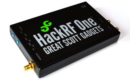
HackRF One · Volume 2
HackRF One Volume 2 — The RF Chain & the Revision Matrix (r1 → r10, plus HackRF Pro)
A schematic-grade walk of the analogue path, with every PCB-revision delta and the upgrade decision tree
2.1 About this Volume
This volume walks the analogue half of a HackRF One — from the SMA connector at the right edge of the board, through the RF switches, the LNA / PA stage, the RFFC5072 mixer, the MAX2837 IF/baseband transceiver, and into the MAX5864 dual ADC/DAC. It is structured as a signal-flow tour following the path of a received photon from antenna to digital sample, then in reverse for the transmit case.
After the schematic walk, §10 covers what changed at every PCB revision (r1 → r10), and §11 puts the HackRF Pro side-by-side with the One on a per-stage basis. §12 closes with a defensible upgrade decision tree.
The digital half — LPC4320, CPLD, SGPIO, USB, clocking — is in Vol 3. The firmware that drives both halves is in Vol 4. This volume assumes you are reading with the HackRF schematic open in another window (it is at https://github.com/greatscottgadgets/hackrf/tree/master/hardware/hackrf-one — hackrf_one_v6_schematic.pdf matches r6 onwards; hackrf_one_schematic.pdf matches r1–r4).
2.2 The Block Diagram
A canonical HackRF One r1–r8 (and r10) signal chain looks like this, omitting the digital domain:
       ┌─────── SMA antenna port ─────────┐
       │                                  │
       │  bias-T (3.3 V or 5 V)           │   ← r9/r10 add a series diode here
       │                                  │
       ▼                                  │
   SKY13350/13453 ──── transmit/receive ─┘
   RF switch          ─── path select
       │
       ├─── RX path ──► MGA-81563 LNA (HackRF Pro path differs) ──► band-select ──► RFFC5072 mixer ──► MAX2837 IF/BB transceiver ──► MAX5864 dual ADC
       │                                                                                                              │
       │                                                                                                              ▼
       │                                                                                                  to CPLD/SGPIO/LPC4320
       │
       └─── TX path ◄── MAX2837 IF/BB transceiver ◄── RFFC5072 mixer ◄── PA driver chain ◄── ───────  ◄── MAX5864 dual DAC
                                                                                                                       ▲
                                                                                                                       │
                                                                                                            from CPLD/SGPIO/LPC4320

                       Si5351C clock generator ──► RFFC5072 reference, MAX5864 sample clock, LPC4320 clock
                       25 MHz crystal ──► Si5351C PLL reference
(The ASCII representation above sketches the topology. A hand-authored SVG block diagram lives at figs/hackrf_one_block.svg and is rendered inline in the HTML build.)
The most consequential things about this topology:
- One analogue chain, multiplexed in time — the SKY13350 (or SKY13453, depending on revision) is a single SP4T switch that routes the antenna port to either the RX LNA, the TX PA driver, or one of two intermediate paths. There is no second receiver; the device is fundamentally half-duplex.
- The mixer is between the antenna and the transceiver — the RFFC5072 does coarse frequency translation (heterodyne the signal of interest down to roughly 2.4 GHz), then the MAX2837 does fine demodulation in its 2.3–2.7 GHz IF window. This dual-conversion architecture is what gives the HackRF its 1 MHz – 6 GHz tuning range with only two analogue PLLs.
- The ADC/DAC is a single dual-channel Maxim MAX5864 at up to 22 MS/s — though the HackRF firmware caps usable rates at 20 MS/s for stability headroom. 8-bit resolution is the dynamic-range bottleneck.
- One reference oscillator in the whole device — a 25 MHz crystal feeds the Si5351C, which then generates everything else. There is no TCXO, no GPSDO unless one is wired into the front-panel CLKIN. The HackRF Pro fixes this; see §11.
2.3 The Antenna Port and the Bias-T
The board’s RF input is a single SMA female connector on the right edge. SMA is a 50 Ω 18-GHz-rated connector — overkill for a 6 GHz design, but cheap and ubiquitous. There is no second port: the same connector is used for both RX and TX, multiplexed by the SKY switch (§4).
2.3.1 The bias-T
Pin 1 of the SMA carries both RF and, optionally, DC bias for an external active antenna or LNA. The bias-T injection is a simple inductor + capacitor network on the board (L36 + C159 in the r6 schematic). Bias voltage is selectable by the firmware between 3.3 V and 5 V, with current-limit circuitry that protects against shorted feeds.
In r9 and r10 there is a series diode on the bias-T’s DC feed. The reason: an external active antenna with a stiff DC short or a wired short during connector mating could backfeed current into the HackRF’s 3.3 V rail, occasionally damaging the regulator. The diode (a Schottky in series) stops backflow at the cost of a ~0.3 V drop on the bias rail. If you intend to feed an active antenna, the r9/r10 boards are mildly safer; on r1–r8 (your r4) the discipline is to confirm continuity with a multimeter before mating the SMA.
2.3.2 Bias-T command reference
From the host, the bias-T is enabled per-direction (RX or TX) via:
hackrf_transfer -r capture.cfile -f 433000000 -s 2000000 -p 1 ...
                                                  ^^^
                                                  enable bias-T (3.3 V on RX path)
Or via libhackrf’s hackrf_set_antenna_enable(). The firmware does not turn the bias on at boot — explicit enablement protects against accidentally feeding voltage into a passive antenna or a dummy load.
Vol 5 §4 covers hackrf_transfer flags in detail; Vol 8 §4 covers what a “needs bias” antenna actually wants to see.
2.4 The RF Switches — SKY13350 vs SKY13453
The single SP4T RF switch behind the SMA connector is the revision-most-touched part in the whole HackRF history. r1–r5 used SKY13350; r6 went to SKY13453; r7 reverted to SKY13350; r8 went back to SKY13453; r9 / r10 stay on SKY13453.
What the switch does
It selects, under firmware control, which of four paths the antenna port is wired to:
- RX path 1 — goes through a band-pass filter network and the MGA-81563 LNA, into the mixer.
- RX path 2 — alternate filtering for the high-band tuning case (above ~2.5 GHz), where the LNA is bypassed.
- TX path 1 — drives the antenna from the PA chain at low/mid bands.
- TX path 2 — drives the antenna from the PA chain at high bands.
The four paths exist because the HackRF One’s wide tuning range is achieved by switching front-end filters — the same design problem you have on any wideband receiver. See §5 for the filter banks.
SKY13350 vs SKY13453
Table 1 — 4.2 SKY13350 vs SKY13453
| Parameter | SKY13350 (r1–r5, r7) | SKY13453 (r6, r8, r9, r10) |
|---|---|---|
| Vendor | Skyworks | Skyworks |
| Topology | SP4T | SP4T |
| Frequency range | 0.1 to 6 GHz | 0.1 to 6 GHz |
| Insertion loss (typ) | 0.5 dB @ 2 GHz | 0.4 dB @ 2 GHz |
| Isolation (typ) | 25 dB @ 2 GHz | 30 dB @ 2 GHz |
| Control | 4-line decoded | 2-line encoded + 1 enable |
| 1-dB compression | +33 dBm | +33 dBm |
The SKY13453 has simpler control logic (encoded path select instead of 1-of-4 decoded) and slightly better insertion loss + isolation. The SKY13453 was originally adopted in r6 to reduce GPIO consumption on the LPC4320; r7 reverted because of supply, r8 went back because supply recovered. The firmware handles both transparently — no behavioural difference is visible at the hackrf_transfer layer.
For your r4: this is a SKY13350. It is fine. Insertion loss of half a dB at the front of an 8-bit-ADC chain is unmeasurable in normal use.
2.5 The Front-End Filters (RX side)
Between the SKY switch and the LNA there is a filter bank that the firmware switches based on the requested centre frequency:
Table 2 — Between the SKY switch and the LNA there is a filter bank that the firmware switches based on the requested centre frequency
| Band | Filter type | Cut-offs (approx) | Used when tuning to |
|---|---|---|---|
| Sub-2.15 GHz LPF | Low-pass | DC – 2.15 GHz | All tunings ≤ 2.15 GHz |
| Above-2.75 GHz HPF | High-pass | 2.75 GHz – 6 GHz | All tunings ≥ 2.75 GHz |
| Mid-band bypass | Direct (no filter) | 2.15 – 2.75 GHz | Band where the IF window itself is the filter |
The mid-band gap is interesting — the HackRF’s IF stage at the MAX2837 is centred at 2.4 GHz (because the MAX2837 is a 2.4 GHz transceiver), so any signal in the 2.15–2.75 GHz range is essentially in-band and does not need additional pre-selection. The mixer’s role at those frequencies is degenerate. The firmware handles this transparently — hackrf_transfer -f 2440000000 does the right thing without you having to think about it.
The filters are commodity LC ladders, not surface-acoustic-wave filters; the rejection is modest (≥30 dB out of band) and the insertion loss is about 1 dB. This is fine for a wideband instrument; it is not the right architecture for a serious receive radio. For weak-signal work below 1 GHz, pair the HackRF with a band-specific external front-end (Vol 8 §5).
2.6 The LNA — MGA-81563
The HackRF One’s RX path uses an Avago MGA-81563 as its first amplifier. This is a vintage GaAs MMIC — the same family of small-signal LNAs Avago/Broadcom produced for cable-TV head-end and 1990s satellite receivers.
Table 3 — 6. The LNA — MGA-81563
| Parameter | MGA-81563 typical | Comment |
|---|---|---|
| Frequency range | 0.1 – 6 GHz | The HackRF uses it across the full band |
| Gain (typ) | ~12 dB @ 2 GHz | Drops to ~6 dB at 5.8 GHz |
| Noise figure | ~3.0 dB @ 2 GHz | ~3.5 dB at 5 GHz |
| 1-dB compression | +6 dBm output | Modest — strong signals will saturate the LNA before the ADC |
| Supply | 5 V, ~30 mA |
The HackRF uses the MGA-81563 in a switchable configuration — for high-band tunings (above ~2.5 GHz), where the LNA’s gain has dropped and its noise figure has risen, the firmware switches the LNA out of the path and feeds the mixer directly. This is cheaper than a band-specific LNA stack and is part of why HackRF performance falls off at the top of the band.
For weak-signal work above 1 GHz, adding an external LNA before the HackRF is one of the highest-leverage upgrades you can make. A Mini-Circuits ZRL-1150LN+ adds 30 dB of gain at <1.5 dB NF for $90; a NooElec SAWbird has band-specific filters built in for $40. Vol 8 §5 covers external-LNA pairing in detail.
2.7 The Mixer — Qorvo RFFC5072
The mixer / synthesizer between the LNA and the MAX2837 is a Qorvo RFFC5072^[Qorvo (formerly RFMD): https://www.qorvo.com/products/p/RFFC5072 — datasheet at https://www.alldatasheet.com/datasheet-pdf/pdf/545968/RFMD/RFFC5072.html.]. This is a single-chip integrated frequency conversion device: an LO synthesizer (fractional-N PLL + VCO) feeding an internal mixer, all in a 5×5 mm 32-pin QFN.
Table 4 — 7. The Mixer — Qorvo RFFC5072
| Parameter | RFFC5072 spec | Significance |
|---|---|---|
| LO range | 85 MHz – 4200 MHz | Used as part of HackRF’s 1 MHz – 6 GHz tuning |
| Mixer usable up to | 6 GHz | The HackRF’s nominal upper limit |
| Step size | 1.5 Hz typical (integer + frac-N) | More than enough resolution |
| Phase noise (1 GHz LO) | 0.18° rms | Adequate for HackRF’s 8-bit resolution |
| Phase noise (3 GHz LO) | 0.50° rms | Same |
| Supply | 2.7 – 3.3 V | Standard digital supply |
The RFFC5072 is programmed over a 3-wire serial interface (clock + data + enable) directly from the LPC4320’s GPIOs. The firmware sets the LO synthesizer to translate the band of interest down to (or up from) the 2.4 GHz IF that the MAX2837 wants to see.
The dual-conversion design has the usual heterodyne-architecture characteristics: image rejection is the limiting factor. The HackRF does not do image-reject mixing in hardware — there is one mixer, not two, and the MAX2837’s complex (I/Q) baseband is what gives image rejection in the digital domain (Vol 6 §4 covers complex demodulation in GRC).
2.8 The Transceiver — MAX2837 (and MAX2839 on r9 only)
The MAX2837 is the single most important chip on the board. It is a complete 2.3 to 2.7 GHz transceiver in a single 7×7 mm 40-pin TQFN — it integrates RX baseband filters, RX gain control, the I/Q demodulator, the I/Q modulator, TX baseband filters, TX gain control, the synthesiser support, and the analogue I and Q outputs that go into the MAX5864.
Table 5 — 8. The Transceiver — MAX2837 (and MAX2839 on r9 only)
| Parameter (RX) | MAX2837 |
|---|---|
| Operating frequency | 2.3 – 2.7 GHz |
| Receive gain range | 0 – 102 dB in 2 dB steps (LNA + VGA + IF) |
| Receive baseband bandwidth | 1.75 / 2.5 / 3.5 / 5 / 5.5 / 6 / 7 / 8 / 9 / 10 / 12 / 14 / 15 / 20 / 24 / 28 MHz |
| Receive noise figure (typ) | 4 dB at minimum gain |
| Receive 1-dB compression | -19 dBm input at max gain |
| Receive image rejection | -40 dB typical |
Table 6 — 8. The Transceiver — MAX2837 (and MAX2839 on r9 only)
| Parameter (TX) | MAX2837 |
|---|---|
| Transmit output | -10 to +5 dBm (programmable) |
| Transmit baseband bandwidth | Same selectable filter as RX |
| Transmit phase noise | -100 dBc/Hz @ 100 kHz offset |
The HackRF One sits the MAX2837 at a fixed centre frequency around 2.4 GHz and uses it as a fine-tune front-end — the RFFC5072 does coarse heterodyning, the MAX2837 does the I/Q demodulation. This is why the HackRF’s tuning is described as “1 MHz – 6 GHz” even though no chip on the board can intrinsically tune that whole range — it is the mixer + transceiver combination that achieves it.
The MAX2837 is programmed over SPI from the LPC4320. The firmware writes register values that select the RX baseband filter bandwidth, the gain stages, the LO frequency offset within the IF, and the I/Q balance trims.
2.8.1 What the MAX2839 substitution changed (r9 only)
In r9 (2023), the global semiconductor shortage forced GSG to substitute the MAX2839 for the MAX2837. The MAX2839 is almost pin-compatible — Maxim/Analog Devices designed it as a drop-in alternative for the MAX2837 — but a small number of register addresses moved, and the Si5351A clock generator (also part of the r9 substitution) needed extra clock distribution to feed the MAX2839 differently. This is why r9 has its own block diagram on the GSG docs^[https://hackrf.readthedocs.io/en/latest/hardware_components.html — separate r9 block diagram exists alongside the r1-r8 / r10 baseline.]: the firmware has to know whether it’s talking to a MAX2837 (r1–r8, r10) or a MAX2839 (r9 only), and the build sets the right register table at compile time.
The performance is not meaningfully different at the user level. Both transceivers achieve essentially the same NF, image rejection, and bandwidth. The MAX2837 was reverted in r10 because (a) supply recovered and (b) GSG preferred to keep the firmware path simple — one transceiver, one register table.
For your r4: this is a MAX2837. No special handling.
2.8.2 The HackRF Pro’s MAX2831
The HackRF Pro replaces the MAX2837 with a MAX2831 — a similar but 2.3 to 2.6 GHz transceiver from the same Maxim family^[https://www.analog.com/en/products/max2831.html. The MAX2831 datasheet covers both the MAX2831 and MAX2832 in one PDF: https://www.analog.com/media/en/technical-documentation/data-sheets/MAX2831-MAX2832.pdf.]. The MAX2831 is more recently spec’d, with somewhat better IIP3, flatter IF response, and tighter I/Q balance. Combined with the Pro’s iCE40 FPGA (which can implement higher-order digital correction), the Pro’s RX flatness is substantially better than the One’s across the full tuning range.
Vol 4 §10 covers Pro-specific firmware paths.
2.9 The ADC/DAC — Maxim MAX5864
The final analogue stage is the MAX5864 — a dual 8-bit ADC + dual 8-bit DAC in one package, capable of 22 MS/s on each channel, complementary CMOS interface to the CPLD.
Table 7 — 9. The ADC/DAC — Maxim MAX5864
| Parameter | MAX5864 |
|---|---|
| ADC resolution | 8-bit (each channel — I and Q separately) |
| ADC sample rate | up to 22 MS/s |
| ADC SNR (typ) | 47 dB at 22 MS/s |
| ADC SFDR (typ) | 60 dB |
| DAC resolution | 8-bit |
| DAC sample rate | up to 22 MS/s |
| DAC settling time | 4 ns |
| Interface | parallel CMOS, 8-bit per direction |
The 8-bit resolution is the fundamental dynamic-range bottleneck of the HackRF One. Theoretical SNR is 6.02 × 8 + 1.76 ≈ 49.8 dB; real-world performance lands at ~48 dB on the bench. This means:
- A signal at -20 dBm at the antenna and a signal at -68 dBm cannot be heard in the same capture without changing the gain settings — the second signal is below the noise floor.
- Strong adjacent-channel signals desensitise the receiver. Tune to a quiet 433 MHz remote with a strong FM broadcast 100 MHz lower, and the FM broadcast eats your dynamic range even though it’s not in your bandwidth of interest.
- Pre-filtering matters more than on a 12-bit SDR — band-pass filters before the HackRF (or active filters in the MAX2837’s selectable bandwidth) are how you keep the dynamic range working for you. Vol 8 §6 covers external filters.
The MAX5864 is the one part the HackRF Pro keeps unchanged from the One — the 8-bit ADC is still the sample stage. The Pro’s improvements are around it (better TCXO, better transceiver, better digital correction in the FPGA), not in it.
2.10 The Revision Matrix in Detail
This expands §4 of Vol 1 (this volume’s parent table) into per-revision detail. The lineage is:
r1 ─── r2 ─── r3 ─── r4 ───┐
                            │
                           r5 (experimental, not shipped)
                            │
                           r6 ─── r7 ─── r8 ─── r9 ─── r10
2.10.1 r1 – r4 (2014–2020) — the original
What’s in your H2R4. Identical hardware design across the four manufacturing runs; revision number was incremented to track the BOM as components went obsolete and were swapped silently during the manufacturing lifecycle (e.g. one capacitor model was replaced with an electrically equivalent part from a different vendor, rev was bumped to track which production batch the BOM-as-built corresponds to).
Components:
- Switches: SKY13350
- LNA: MGA-81563
- Mixer: RFFC5072
- Transceiver: MAX2837
- ADC/DAC: MAX5864
- Clock generator: Si5351C
- Reference: 25 MHz crystal
- MCU: LPC4320FBD144
- CPLD: Xilinx CoolRunner-II XC2C64A
- Flash: Winbond W25Q80BV (8 Mbit)
- USB: micro-USB
2.10.2 r5 — experimental, not manufactured
Listed in the GSG docs for completeness. Whatever changes were prototyped in r5 went into the production r6 if they survived; r5 itself never shipped.
2.10.3 r6 (2020) — switch change + revision-strap pins
- SKY13350 → SKY13453 (simpler control logic)
- Hardware revision strap pins added — three strap-tied GPIOs on the LPC4320 are read at boot and reported through
hackrf_infoso firmware knows the rev. r1–r4 cannot self-report (the firmware reads the pins as floating); r6 onwards reports rev correctly.
2.10.4 r7 (2021) — switch reverted, USB tweaks
- SKY13453 → SKY13350 (supply recovered)
- USB VBUS detection resistor values updated — fixes a sporadic enumeration issue on certain hosts.
2.10.5 r8 (2021–2022) — switch change, again
- SKY13350 → SKY13453 (supply went away again)
2.10.6 r9 (2023) — the chip-shortage rev
This is the revision most affected by the global semiconductor shortage. Three changes:
- MAX2837 → MAX2839 (transceiver substitution)
- Si5351C → Si5351A with additional clock distribution added to the board to compensate
- Series diode added at antenna-port DC bias feed (safety improvement)
The MAX2839 substitution required firmware changes — the build now ships per-revision register tables. Performance is essentially unchanged; the change exists purely because GSG could not source MAX2837 in the volume needed, and Maxim had spec’d the MAX2839 as an intentional drop-in alternative.
2.10.7 r10 (2024+) — revert to baseline + keep the diode
The current shipping revision. Changes:
- MAX2839 reverted to MAX2837 (supply recovered; GSG prefers single-transceiver firmware)
- Si5351A reverted to Si5351C (supply recovered)
- Diode kept at the antenna-port bias feed
This is, electrically, r8 + the bias-T diode. r10 is the closest current GSG part to your r4. The differences r4 → r10 are: SKY13453 instead of SKY13350 (no behavioural difference); revision strap pins (no behavioural difference at the user level — hackrf_info reports a rev now); diode at bias-T (matters only if you intend bias-T-fed active antennas).
2.10.8 The “should I upgrade r4 → r10?” decision
Table 8 — 10.8 The "should I upgrade r4 → r10?" decision
| Reason to upgrade | Worth it? |
|---|---|
| Bias-T safety (intend to use active antennas) | Modest — the discipline of multimeter-checking the antenna before mating fully compensates |
| Newer silicon with better tolerances | No — the silicon is the same |
| Firmware-reported revision | No — hackrf_info reporting “r4” is fine; the device is r4 |
| Manufacturing freshness | Marginal — modern boards may have better solder joints |
| Resale value preserved | Maybe — r10 holds its value better |
Recommendation: do not upgrade r4 → r10 absent a specific need. If the r4 dies or you want a second device for synchronised dual-receiver work, get an r10. Otherwise the r4 is the device. The much more interesting upgrade is to a HackRF Pro (next section) — but that is a different conversation.
2.11 The HackRF Pro vs HackRF One — a Per-Stage Comparison
This expands Vol 1 §5 into stage-by-stage detail.
Table 9 — 11. The HackRF Pro vs HackRF One — a Per-Stage Comparison
| Stage | HackRF One (r1-r8, r10) | HackRF Pro | Practical effect |
|---|---|---|---|
| Antenna port | SMA female, 50 Ω, 18 GHz | Same | No change |
| Bias-T | 3.3 V / 5 V (diode on r9/r10) | Same | No change |
| RF switch | SKY13350 / SKY13453 SP4T | SKY13453 SP4T | Slight insertion-loss improvement on Pro |
| LNA | MGA-81563 GaAs MMIC | Newer MMIC (datasheet TBD as of 2026-05) | Better NF and gain flatness |
| Front-end filters | LC ladder bands | Same approach, finer band split | Slightly better out-of-band rejection |
| Mixer / synthesizer | RFFC5072 (85 MHz – 4.2 GHz LO) | Same (still RFFC5072) | No change |
| Transceiver | MAX2837 (or MAX2839 on r9) | MAX2831 (newer, flatter, better IIP3) | Better RX dynamic range; lower IM3 |
| Lower frequency limit | 1 MHz | 100 kHz operating; 0 Hz tunable | HF directly without upconverter |
| Reference | 25 MHz crystal | TCXO | Sub-ppm stability |
| ADC/DAC | MAX5864 8-bit dual | Same MAX5864 8-bit | No change at the sample stage |
| Sample rate (initial) | 20 MS/s | 20 MS/s, with planned wider modes | Future-proof software path |
| Glue logic | Xilinx CoolRunner-II XC2C64A CPLD | Lattice iCE40 UltraPlus FPGA | Headroom for digital correction modes |
| Flash | Winbond W25Q80BV (8 Mbit) | Winbond W25Q32 (32 Mbit) | 4× firmware budget; new feature space |
| USB | micro-USB | USB-C | Modern cable; faster charging supported |
| Half / full duplex | Half | Half | No change |
| MSRP | ~$300 | ~$400 | $100 premium |
The Pro’s design philosophy is conservative: keep the mixer-then-transceiver-then-MAX5864 architecture (it works), upgrade everything around it (better LNA, TCXO, flatter transceiver, FPGA instead of CPLD, more flash). This means existing software runs unchanged in legacy mode (Vol 1 §5; Vol 4 §10 covers the firmware-level details), and future firmware drops can layer in extended-precision modes that exploit the FPGA’s digital-correction headroom without breaking compatibility.
The 8-bit ADC is explicitly preserved — Mike Ossmann said publicly during the Pro launch that going to 12-bit would have meant a redesign of the entire pipeline (different ADC, different CPLD/FPGA, different USB throughput needs) and would have priced the Pro at $700+ rather than $400. The Pro is a “fix everything around the 8-bit ADC” device, not a “replace the 8-bit ADC” device. For 12-bit-class work, the right answer is a different SDR (Airspy HF+ Discovery, SDRplay RSPdx, or a USRP).
2.12 The Upgrade Decision Tree
Here is the synthesised decision tree:
Do you intend to do significant HF work below 1 MHz?
│
├── No → next question
│
└── Yes → Two paths:
    │
    ├── Already have a Ham-It-Up upconverter? → Stay with the r4. The
    │   upconverter does the job for $50.
    │
    └── No upconverter? → Buy the HackRF Pro ($400). Direct HF reception
        is significantly cleaner than upconverter-mediated, and the
        TCXO solves the related drift problem.

Do you make absolute-frequency claims regularly (RF compliance, GPS
disciplined references, ham-radio digital modes that need stable
carriers)?
│
├── No → next question
│
└── Yes → Two paths:
    │
    ├── Have an external 10 MHz GPSDO already? → Stay with the r4 +
    │   GPSDO. The CLKIN port + Si5351C lock-up handles this well.
    │
    └── No GPSDO? → HackRF Pro ($400) is cheaper and self-contained.

Has the r4 hardware degraded (front-end damage, dropped on the floor,
strange behaviour above 4 GHz that wasn't there before)?
│
├── No → next question
│
└── Yes → Buy an r10 ($300) for a like-for-like replacement, OR a Pro
    ($400) if any of the above questions also said yes.

Do you want a SECOND HackRF for synchronised dual-receiver work (TDOA,
direction finding, two-channel I/Q analysis)?
│
├── No → done; stay with the r4 + H2.
│
└── Yes → Buy an r10 ($300). Two HackRFs synchronise via a shared 10 MHz
    reference (Vol 5 §7 covers `hackrf_clock`). Buying a Pro for this
    case is overkill — you don't need two TCXOs, only one shared
    reference.

The PortaPack upgrade question is independent (Vol 9):
│
├── Is the H2's mirror-prone screen / phantom drain / lack of battery
│   info a daily friction? → Buy H4M ($+50–100), keep the HackRF One.
│
└── Otherwise → Stay with the H2.
2.13 Bench-Test Procedure (genuineness + revision sanity)
Before every serious project, a five-minute bench test confirms the unit is genuine, on the rev you think it is, and behaving on-spec:
# 1. USB enumeration
$ lsusb | grep -i hackrf
Bus 003 Device 005: ID 1d50:6089 OpenMoko, Inc. HackRF One

# 2. Firmware revision report
$ hackrf_info
hackrf_info version: 2026.01.1
libhackrf version: 0.9 (2026.01.1)
Found HackRF
Index: 0
Serial number: 0000000000000000457863c834a45c0f
Board ID Number: 2 (HackRF One)
Firmware Version: 2026.01.1
Part ID Number: 0xa000cb3c 0x004f4747
Hardware Revision: r4 (read from strap pins; for r1-r5 silkscreen is
authoritative)

# 3. Sweep test (confirms RX path, mixer, ADC working)
$ hackrf_sweep -f 80:1000 -w 100000 -n 8192 -a 1 -l 16 -g 20 -1 \
       > sweep_test.csv
# Look at sweep_test.csv with a plotting tool. Should show ~-95 dBm
# noise floor with FM broadcast peaks at 88-108 MHz at -50 to -30 dBm
# in any urban area.

# 4. Loopback test (confirms TX path, DAC, switching)
$ hackrf_transfer -t /dev/zero -f 433000000 -s 2000000 -x 0
# Wait 5 seconds, then Ctrl-C.
# A spectrum analyser (or a second SDR) shows a tone at 433 MHz on
# transmit. With nothing connected to the SMA, the TX power dissipates
# in the internal switch — fine for a quick sanity check.

# 5. Reference clock check (confirms Si5351C, oscillator)
$ hackrf_clock -i
# Reports the 10 MHz reference state. Should say "Internal" unless an
# external reference is attached.
If any of the five steps fails, see Vol 4 §8 (firmware troubleshooting) and Vol 5 §10 (CLI troubleshooting).
2.14 Cheatsheet Updates from this Volume
These items belong on the field card (Vol 12):
- USB IDs: 1d50:6089 (HackRF One running), 1d50:6088 (DFU), 1d50:cc15 (rad1o badge variant)
- Revision strap-pin readout: only valid on r6+
- r9 is the only rev that runs MAX2839; everything else is MAX2837
- Bias-T diode added on r9 and kept on r10
- RFFC5072 LO range: 85 MHz – 4.2 GHz
- MAX2837 IF: 2.3 – 2.7 GHz (HackRF One); MAX2831: 2.3 – 2.6 GHz (HackRF Pro)
- 8-bit ADC theoretical SNR: ~50 dB
- HackRF Pro lower frequency limit: 100 kHz operating, 0 Hz tunable
2.15 Resources
Table 10 — 15. Resources
Comments (0)