SquachWatch · Volume 2
SquachWatch Volume 2 — Hardware
The Cheap Yellow Display taken apart on paper, pin by pin, and every other board SquachWatch runs on, compared
2.1 The board in context
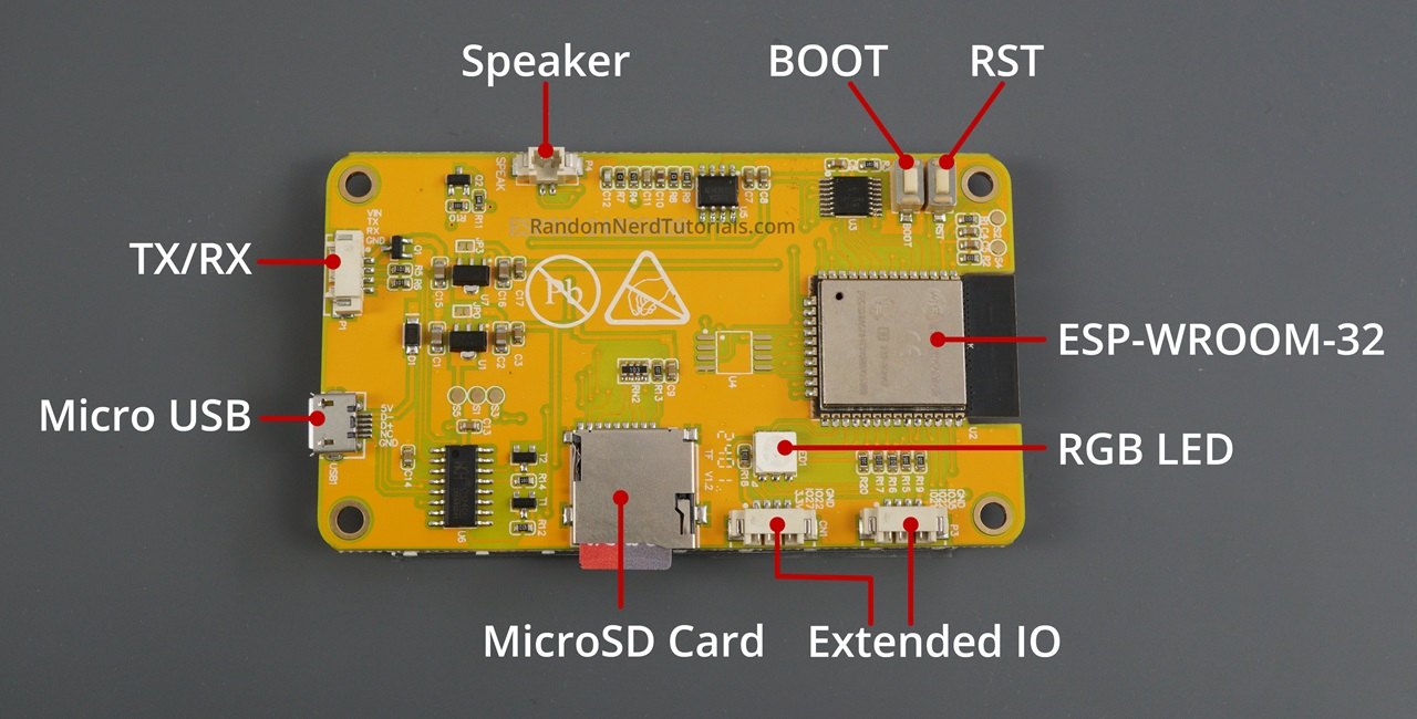
The ESP32-2432S028R is one of a family of Shenzhen Sunton (and clone) ESP32 display boards. The part number encodes the board: 2432 is the 240×320 resolution, S028 the 2.8” glass, and the trailing letter the touch type: R for resistive (XPT2046), C for capacitive, N for none. The maker community named it the Cheap Yellow Display (CYD) after its yellow solder mask; the name is generally credited to Brian Lough (witnessmenow), whose GitHub repository is the de facto reference for the board.
SquachWatch’s author designs on this board first: “The 2.8” CYD (ESP32-2432S028R) is about $15 and is the board everything here is designed on: built-in 320×240 TFT, resistive touch, a microSD slot and an RGB light, and nothing else to add.”
  ESP32-2432S028R — block diagram (as SquachWatch uses it)
  ════════════════════════════════════════════════════════════════════════
   USB ──► CH340 ──UART0 (GPIO1/3)──┐            ┌── HSPI ──► 2.8" TFT
   5 V ──► LDO ─► 3.3 V             │            │   (12/13/14/15, DC 2,
                                    ▼            │    BL 21 PWM)
                       ┌───────────────────────┐ │
   BOOT (GPIO0) ──────►│   ESP32-WROOM-32       │─┤
   RST (EN) ──────────►│   2 × LX6 @ 240 MHz    │ ├── own SPI ─► XPT2046 touch
                       │   520 KB SRAM          │ │   (25/32/39, CS 33,
   LDR ──► GPIO34 ────►│   4 MB SPI flash       │ │    IRQ 36)
                       │   Wi-Fi 2.4 + BT 4.2   │ │
   RGB LED ◄─ 4/16/17 ─│   PCB antenna          │ └── VSPI ──► microSD
   Speaker ◄─ 26 ─amp ─│                        │     (18/19/23, CS 5)
                       └───────────────────────┘
   Free on connectors: GPIO22, GPIO27 (CN1), GPIO35 input-only (P3)
  ════════════════════════════════════════════════════════════════════════
2.2 The ESP32-WROOM-32 and its memory
2.2.1 The silicon
Table 1 — 2.1 The silicon
| Parameter | Value | Note for SquachWatch |
|---|---|---|
| Module | ESP32-WROOM-32 (ESP32-D0WD family) | PCB trace antenna; no external antenna connector on the standard board |
| CPU | 2 × Xtensa LX6, up to 240 MHz | CPU CLOCK in POWER SAVER lowers it (Vol 8) |
| SRAM | 520 KB on-chip, no PSRAM | The constraint behind almost every engineering note in the repo |
| Flash | 4 MB SPI | Two OTA slots of 1.92 MB each |
| Wi-Fi | 802.11 b/g/n, 2.4 GHz only | Promiscuous RX for detection; STA only for the update check |
| Bluetooth | BT 4.2: BR/EDR (Classic) + BLE | Only BLE is used (NimBLE observer + broadcaster) |
| Radio sharing | One 2.4 GHz RF path shared by Wi-Fi and BT via coexistence | Wi-Fi and BLE time-share, which bounds how much of each is heard |
The project’s original design contract describes the MCU as “single Xtensa LX6 core, 240 MHz, 320 KB RAM, no PSRAM.” The “single core” wording is wrong for the WROOM-32: its ESP32-D0WD die is dual-core, and the project’s own NM-CYD-C5 notes compare it as “Xtensa LX6, dual-core 240 MHz.” DESIGN.md warns that it should be read as history (“where this file and the code disagree, the code is right”). The 320 KB figure is a fair estimate of the DRAM actually available to an Arduino application out of the 520 KB total.
2.2.2 Why memory dominates the design
With no PSRAM, every byte of heap is contested by the Wi-Fi driver, the NimBLE host, the frame buffer and the UI. The platformio.ini comments record real failures from this:
- The CLEAR screen’s frame-buffer reallocation on rotate failed on hardware because “heap fragmentation from WiFi/BLE churn ate the last few KB of the contiguous block it needs.” The fix was to compile out unused NimBLE roles.
- The broadcaster role came back for SquachMesh in v1.5.23 after a one-hour soak on an ST7789 board showed no rotate failure. ILI9341 and AWOK boards had not been soaked with that set.
- On 2026-09-26 the CYDs dropped Bluetooth OTA entirely: “the GATT server behind them was the one part of the Bluetooth stack a CYD carried for nothing else.” The ESP32-S3 boards keep it because “it has room.”
- The DIAGNOSTICS screen reports the largest free contiguous block, “the number to look at if a board starts failing to rotate.”
The UI renders into an 8-bit palettised sprite and converts it to RGB565 on push. That halves the frame buffer, at a measured CPU cost of about 7.3 ms per frame (§3.3).
2.2.3 Flash layout
  4 MB flash — partitions_ota.csv (CYD family, StickS3, Cardputer ADV)
  ┌────────┬──────────┬─────────┬───────────────────┬───────────────────┬──────────┐
  │ boot + │ NVS      │ otadata │ app0 (ota_0)      │ app1 (ota_1)      │ coredump │
  │ ptable │ 0x9000   │ 0xE000  │ 0x10000           │ 0x1F0000          │ 0x3F0000 │
  │        │ 20 KB    │ 8 KB    │ 1.875 MB          │ 1.875 MB          │ 64 KB    │
  └────────┴──────────┴─────────┴───────────────────┴───────────────────┴──────────┘
    settings, PIN,      which     running / trial      the other slot:     crash
    squad key, Wi-Fi    slot      image                update target and   record
    passwords, touch    boots                          SWITCH TO target
    calibration
Source: partitions_ota.csv. There is no SPIFFS or LittleFS partition: “SD logging goes to a real card, not internal flash.” The 16 MB ESP32-S3 boards use partitions_twatch.csv, which keeps the NVS and otadata offsets but gives each app slot 4 MB (0x400000) and moves the coredump to 0x830000.
Warning — NVS sits between the bootloader and the app slots. Writing a merged factory image from offset 0x0 pads that gap with 0xFF and erases settings, PIN, squad key and touch calibration. The web flasher stopped serving the merged image for exactly this reason, and the NM-CYD-C5 notes repeat the warning for hand flashing with esptool. Vol 5 covers the safe procedure.
2.3 The display
2.3.1 Two controllers, one board
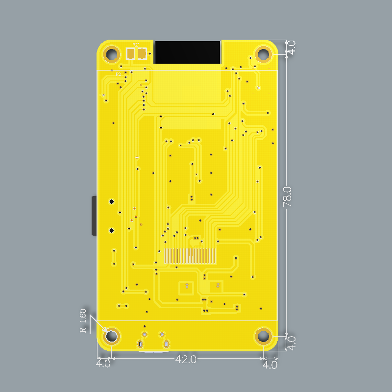
The 2.8” CYD ships with either a Sitronix ST7789 or an Ilitek ILI9341 controller behind identical glass and identical wiring, “depending on manufacturing batch … and there’s no way to tell which from the outside.” SquachWatch therefore ships two builds that differ only in the TFT_eSPI setup header:
Table 2 — The 2.8" CYD ships with either a Sitronix ST7789 or an Ilitek ILI9341 controller behind identical glass and identical wiring, "depending on manufacturing batch … and there's no way to tell which from the outside." SquachWatch therefore ships two builds that differ only in the TFTeSPI setup header
| Item | cyd (ST7789) | cyd-ili9341 (ILI9341) |
|---|---|---|
| Header | include/cyd_user_setup.h | include/cyd_ili9341_user_setup.h |
| Driver define | ST7789_DRIVER | ILI9341_DRIVER |
| Colour order | TFT_BGR | TFT_RGB |
| Inversion | off | off |
| SPI clock | 40 MHz (80 MHz in cyd-fast) | 40 MHz (80 MHz in cyd-ili9341-fast) |
| Web flasher default | 80 MHz box ticked | Leave 80 MHz unticked |
| Also used for | n/a | ESP32-32E 2.8” (E32R28T) |
| Status per project | ”default/more-commonly-reported variant" | "older panel batch” |
Wrong driver gives a solid white screen, which is not a fault: flash the other build. Wrong colour order or inversion gives a negative or swapped-red/blue picture, which is fixed at runtime with Settings → SYSTEM → CHECK COLORS (INVERT and ORDER), also offered on first boot.
Third-party guidance generally associates the original micro-USB CYD with the ILI9341 and the later two-port “CYD2USB” revision with the ST7789 (which needs inversion, per that source). SquachWatch’s cyd header sets inversion off and the CHECK COLORS screen exists precisely because batches vary, so the rule of thumb is a starting guess, not a guarantee.
2.3.2 Display pins
Table 3 — 3.2 Display pins
| Signal | GPIO (from the compiled headers) |
|---|---|
| MOSI | 13 |
| MISO | 12 |
| SCLK | 14 |
| CS | 15 |
| DC | 2 |
| RST | not driven (-1, power-on reset) |
| Backlight | 21, LEDC PWM at 5 kHz, 8-bit duty |
Note —
docs/PINOUT.mdin v1.36.0 labels the TFT bus “VSPI” and lists MOSI as GPIO 27, which conflicts with both the headers that are actually compiled (TFT_MOSI 13,TFT_MISO 12) and the witnessmenow pin map (display on HSPI: 12/13/14/15/2). The same document’s own “pins in use” table lists 12 and 13 as “display bus” and 27 as free. The compiled headers are authoritative; the table above follows them.
2.3.3 Clock and frame rate
The 80 MHz builds are a deliberate overclock. The header comment explains: “the ST7789’s rated write cycle is ~16ns, about 62.5MHz … The ESP32 SPI divider snaps to 80/40/26.7/20, so there is no intermediate value to retreat to: it is 40 or 80.” Its measurements on real hardware:
Table 4 — The 80 MHz builds are a deliberate overclock. The header comment explains: "the ST7789's rated write cycle is ~16ns, about 62.5MHz … The ESP32 SPI divider snaps to 80/40/26.7/20, so there is no intermediate value to retreat to: it is 40 or 80." Its measurements on real hardware
| Clock | Push time | Frame time | Frame rate |
|---|---|---|---|
| 40 MHz | 38 ms | 44.4 ms | ~22 fps |
| 80 MHz | 22.6 ms | 29 ms | ~34 fps |
About 30.7 ms of the 40 MHz push is the bus itself (153,600 bytes at 16 bpp); the remaining ~7.3 ms is the 8 bpp → RGB565 palette conversion, which does not scale with the SPI clock. That explains the 1.7× speed-up rather than 2×. Overclock failures (white screen, torn lines, colour corruption) “look identical to the wrong-driver problem”, which is why the flasher keeps the overclock as a separate, reversible checkbox.
2.4 Touch, SD card and the three SPI buses
2.4.1 Bus topology
The classic CYD gives the display, the touch controller and the SD card three separate SPI paths. Other boards share them, and that difference drives several build flags.
  Classic 2.8" CYD                           RL Phantom-R / NM-CYD-C5 / AWOK / Marauder V8
  ─────────────────                          ──────────────────────────────────────────────
  HSPI  ─► TFT          (12/13/14)           one SPI ─┬─► TFT
  soft/2nd SPI ─► XPT2046 (25/32/39, CS33)            ├─► XPT2046 (CS only, raw reads)
  VSPI  ─► microSD      (18/19/23, CS5)               └─► microSD (CS only)
                                             → -DRLPHANTOM_R / TOUCH_RAW_SHARED_BUS
2.4.2 Touch (XPT2046)
Table 5 — 4.2 Touch (XPT2046)
| Signal | GPIO |
|---|---|
| CS | 33 |
| IRQ | 36 (input-only) |
| MOSI | 32 |
| MISO | 39 (input-only) |
| SCLK | 25 |
Source: src/main.cpp TOUCH_* defines and docs/PINOUT.md. The library is Paul Stoffregen’s XPT2046_Touchscreen on the classic board; shared-bus boards read raw values off the display’s bus instead. Resistive touch needs calibration: SquachWatch runs a five-target routine at first boot (since v1.17.0), stores it in NVS, and “one calibration covers all four rotations.” Holding a finger on the screen during the boot prompt resets a bad calibration. A touch held for more than about half a second without moving is ignored as a tap.
2.4.3 microSD
Table 6 — 4.3 microSD
| Signal | GPIO |
|---|---|
| CS | 5 |
| MOSI | 23 |
| MISO | 19 |
| SCLK | 18 |
The card is optional: “if no card is inserted at boot, the firmware just skips SD logging and everything else works.” BUILD.md asks for FAT32. The firmware limits the FAT driver to two open files rather than the library default of five, which saves RAM. On the Freenove ESP32-S3 boards the slot is 4-bit SDMMC rather than SPI; the firmware mounts 4-bit and falls back to 1-bit.
2.5 The small parts
Table 7 — 5. The small parts
| Part | GPIO | What SquachWatch does with it |
|---|---|---|
| RGB LED (back of board) | R 4, G 16, B 17; common anode, LOW = on | The status light: breathe when idle, three flashes + hold in the detection’s colour, double-blink for unread messages, cyan/green/red for updates. LEDC channels 3–5 (backlight owns 0–2) |
| LDR (light sensor) | 34 (input-only ADC) | Only an analogRead() to seed the PRNG for the digital rain on Xtensa boards; no auto-brightness in v1.36.0 |
| Speaker connector (P4, 2-pin) | 26, through an on-board amplifier | Not used on the CYD. Sound exists only on the Freenove S3 boards (ES8311 codec) |
| BOOT button | 0 | Short press: screen off (POCKET MODE, only BOOT wakes it). Hold ~1 s: CHARGE MODE (radios, light, screen off) |
| RST button | EN | Hardware reset |
| USB serial | 1 (TX), 3 (RX) | Console at 2,000,000 baud: TIME, ZONE, GPS …, WARDRIVE … commands |
Tip — GPIO 4 is the red channel of the status light on the classic CYD. Some look-alike boards put something else on GPIO 4. On the ESP32-32E boards, for example, LCDwiki documents GPIO 4 as the speaker amplifier enable and the RGB LED on 22/16/17. The repo routes the E32R28T to the
cyd-ili9341build without commenting on its LED pins, so the status light’s red channel on that board is unverified. The repo’s own caution applies: “driving PWM onto a pin that turns out to be something else is exactly how the Phantom’s touch fault happened.”
2.6 USB, power and connectors
2.6.1 USB and serial
Most CYDs use a CH340-family USB-serial bridge, which “Windows usually needs its driver” for. On this chip the console has been confirmed clean at 2,000,000 baud; boards with a CP210x (AWOK, Marauder V8) are left at lower rates because “AWOK’s CP210x garbles at 2000000.” Auto-reset into the bootloader is normally handled by the bridge’s DTR/RTS lines; when it is not, holding BOOT while plugging in forces download mode.
2.6.2 Power
Table 8 — 6.2 Power
| Item | Classic 2.8” CYD |
|---|---|
| Supply | 5 V via USB, or VIN on the P1 serial connector |
| Regulation | On-board LDO(s) to 3.3 V; witnessmenow lists separate ESP32 and TFT 3.3 V test points (S2, S5) |
| Battery / charger | None on the classic board |
| Battery indication | None. The original contract lists “no battery monitoring”; the lava-lamp gauge appears only on the Freenove S3 boards, the T-Watch and boards with a gauge |
| USB-C quirk | The two-port CYD2USB revision’s USB-C lacks CC pull-downs, so C-to-C cables may not power it; use A-to-C |
Battery operation of a classic CYD therefore means external parts: a USB power bank, or a single-cell LiPo with a charger and a 5 V boost feeding VIN. Vol 3 lists the parts and Vol 4 the wiring. Look-alikes such as the ESP32-32E E32R28T add a 2-pin LiPo connector and an on-board TP4054 charger (§7.3).
2.6.3 Connectors
All are 4-pin 1.25 mm (Molex PicoBlade-style, often sold as “MX1.25”) except the 2-pin speaker.
  ┌──────────── CYD expansion connectors ───────────────────────────────┐
  │  P1  (serial)   VIN │ GPIO1 TX │ GPIO3 RX │ GND                      │
  │  P3  (GPIO)     GND │ GPIO35 (in only) │ GPIO22 │ GPIO21 (backlight!)│
  │  CN1 (I²C-ish)  GND │ GPIO22 │ GPIO27 │ 3.3 V                        │
  │  P4  (speaker)  2-pin, driven from GPIO26 through the amplifier      │
  └─────────────────────────────────────────────────────────────────────┘
  SquachWatch uses: P3 GPIO35 = GPS TX in (cyd-gps builds)
                    CN1 3.3 V / GND = GPS power (cyd-gps builds)
                    GPIO27 is driven HIGH at boot by the firmware
The spare pins, per the firmware: “GPIO 22 and 35. GPIO 27 on CN1 is also free, but the firmware drives it high at boot. GPIO 35 is input only.” The optional GPS build reads an ATGM336H at 9600 baud on GPIO 35, with the module’s RX unconnected, so the firmware runs it on its defaults and cannot configure it (Vol 4).
2.7 Every supported board compared
2.7.1 The master table
Status columns follow README.md and docs/FAQ.md at v1.36.0. “Flasher” means a build on squachwatch.com.
Table 9 — 7.1 The master table
| Board | Env | MCU | Display | Touch | SD | Light | Battery | Extra radios | Flasher |
|---|---|---|---|---|---|---|---|---|---|
| 2.8” CYD ESP32-2432S028R (ST7789) | cyd / cyd-fast | ESP32 | 240×320 ST7789 | XPT2046 | SPI | RGB 4/16/17 | — | — | Yes |
| 2.8” CYD (ILI9341) / E32R28T | cyd-ili9341 | ESP32 | 240×320 ILI9341 | XPT2046 | SPI | RGB | — | — | Yes |
| 3.2” capacitive ESP32-2432S032C | cyd32c | ESP32 | ST7789 IPS | GT911 | SPI | — | — | — | Yes (80 MHz) |
| 3.2” resistive Freenove FNK0103 | freenove32 | ESP32 | ST7789 IPS | XPT2046 shared | SPI | — | — | — | Yes |
| RL Phantom 2.4” ESP32-2432S024R | rlphantom-r | ESP32 | ILI9341 | XPT2046 shared | SPI | RGB, front | Pre-built pack | — | Yes |
| AWOK 2.4” (Marauder V6.1) | awok | ESP32 | ILI9341 | XPT2046 shared | SPI | compiled out | — | — | Yes |
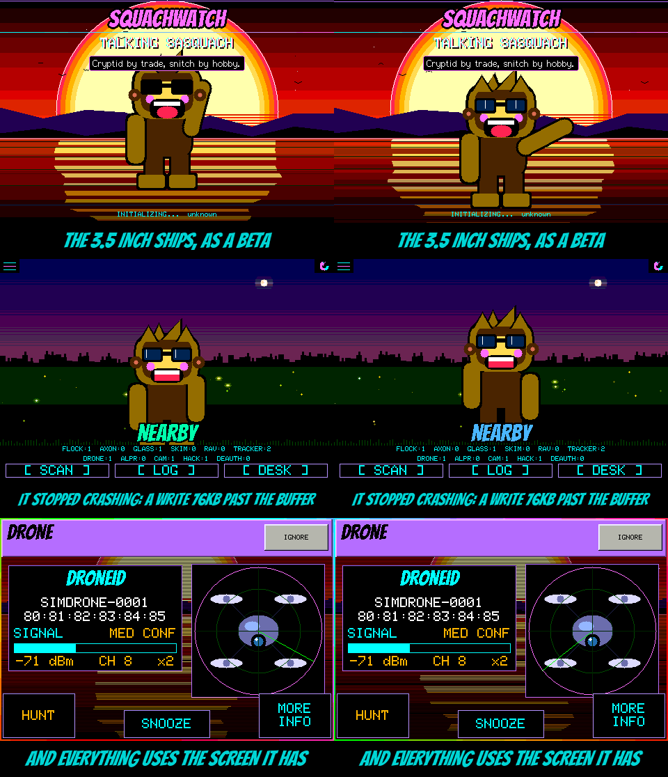
| 3.5” ESP32-3248S035R / E32R35T | cyd35-fast | ESP32 | 320×480 ST7796 | XPT2046 shared | SPI | compiled out | — | — | BETA |
| 3.5” capacitive ESP32-3248S035C | cyd35c-fast | ESP32 | 320×480 | GT911 | SPI | — | — | — | BETA |
| Freenove ESP32-S3 2.8” FNK0104B | freenove-s3 | ESP32-S3R8 | ILI9341 | FT6336 | SDMMC | WS2812 | Connector + gauge | — | BETA |
| Freenove ESP32-S3 3.5” FNK0104N | freenove-s3-35 | ESP32-S3 | 320×480 QSPI | capacitive | SDMMC | WS2812 | Connector + gauge | — | BETA |
| Freenove ESP32-S3 4.0” FNK0104S | freenove-s3-40 | ESP32-S3 | 320×480 ST7796 | FT6336 | SDMMC | WS2812 | Connector | — | Source only |
| Elecrow CrowPanel Advance 7.0 | crowpanel7 | ESP32-S3-N16R8 | 800×480 RGB (drawn 400×240 ×2) | GT911 | yes | — | — | (LoRa module researched) | BETA |
| RockBase NM-CYD-C5 | nm-cyd-c5 | ESP32-C5 | ST7789 | XPT2046 shared | SPI | WS2812 | — | 5 GHz Wi-Fi | BETA |
| Marauder V8 | marauder-v8 | ESP32-C5 | ILI9341 | XPT2046 shared | SPI | single LED | MAX17048 gauge | 5 GHz, GPS | BETA |
| LilyGo T-Deck Plus | tdeck-plus | ESP32-S3FN16R8 | 320×240 ST7789 | GT911 + keyboard | SPI | — | 2000 mAh | GPS (LoRa not in v1.36.0) | BETA |
| M5Stack StickS3 | sticks3 | ESP32-S3-PICO-1 | 1.14” 135×240 | 2 buttons | — | — | internal | — | BETA |
| M5Stack Cardputer ADV | cardputer-adv | ESP32-S3FN8 | 1.14” 135×240 | keyboard | SPI | — | cell on divider | — | BETA |
| LilyGo T-Watch S3 | twatch-s3 | ESP32-S3 | 1.54” 240×240 ST7789 | FT6336 | — | — | AXP2101 + cell | LoRa RX | BETA |
| LilyGo T-Watch S3 Plus | twatch-s3 | ESP32-S3 | 240×240 | FT6336 | — | — | ~2× S3 cell | LoRa RX + GPS | BETA |
Sources: README.md “Boards”; docs/FAQ.md “Which board should I buy?”; platformio.ini env comments; include/*_user_setup.h headers; docs/PINOUT.md; docs/NM-CYD-C5.md; docs/CROWPANEL7.md. A dash means the repo does not list the feature for that board. The capacitive RL Phantom (rlphantom) builds in CI but “has never run on a real board” and is not published.
2.7.2 Radio capability matrix
Table 10 — 7.2 Radio capability matrix
| Capability | ESP32 boards (CYD family, AWOK, Phantom) | ESP32-S3 boards | ESP32-C5 boards | T-Watch S3 / Plus |
|---|---|---|---|---|
| 2.4 GHz Wi-Fi promiscuous | Yes | Yes | Yes | Yes (duty-cycled by RADIOS setting) |
| 5 GHz Wi-Fi | No | No | Yes (WIFI BANDS: 2.4+5 / 2.4) | No |
| BLE scan | BT 4.2 | BLE 5 | BLE 5.3 | BLE 5 |
| BT Classic in silicon | Yes (unused) | No | No | No |
| BLE OTA update | Dropped (v1.22.0) | Yes (BETA) | n/a in docs | Yes (BETA) |
| LoRa receive | No | No | No | Meshtastic + MeshCore, 868/915 MHz |
| GPS | Only cyd-gps source builds | T-Deck Plus | Marauder V8 | S3 Plus (u-blox MIA-M10Q or LS550G) |
| 802.15.4 | No | No | In silicon, unused | No |
2.7.3 Notes per family
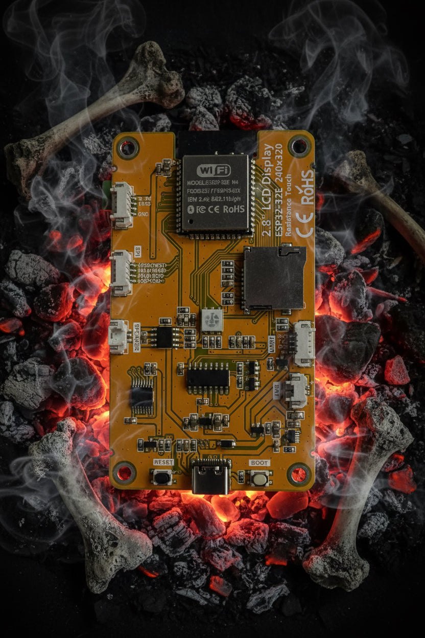
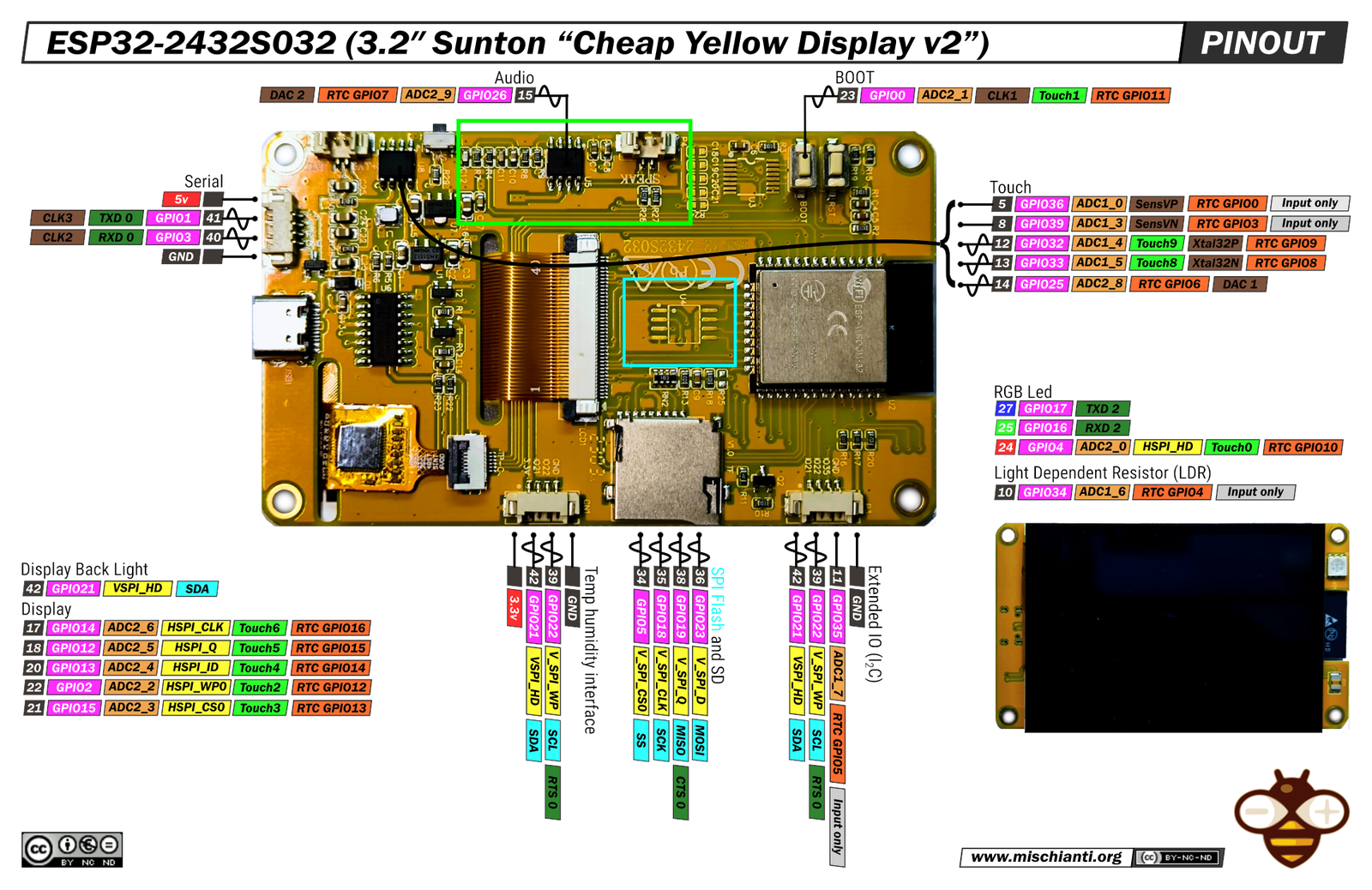
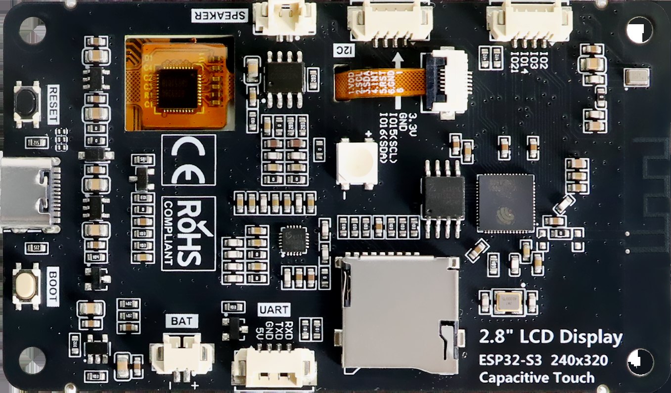
ESP32-32E boards (E32R28T, E32R35T). These are LCDwiki-documented look-alikes, sold among others by HaleHound as the “2.8” CYD E32R28T Exposed SPI.” The flasher’s board finder maps the E32R28T to the 2.8” ILI9341 build and the E32R35T to the 3.5” resistive build. Per LCDwiki the E32R28T carries an ESP32-32E (ESP32-D0WD-V3) module, an ILI9341V panel, a CH340C, USB-C, a 2-pin 1.25 mm LiPo connector with a TP4054 charger, an FM8002E speaker amplifier (enable on GPIO 4) and the RGB LED on 22/16/17. SquachWatch does not read its battery voltage.
RL Phantom 2.4”. A Sunton ESP32-2432S024 with “the SAME display wiring as the 2.8” board — smaller glass, identical pins,” except the backlight on GPIO 27. It ships either capacitive (S024C, CST820) or resistive (S024R, XPT2046 on the display’s bus); only the resistive build is on the flasher. Rabbit Labs sells it pre-built with a battery and case (Vol 3).
The 3.5” ESP32-3248S035R. Frozen. “As of 2026-09-03 the 3.5” board BOOT LOOPS on real hardware” with a NimBLE LoadStoreAlignment panic, suspected to come from display, touch and SD sharing VSPI. The cyd35-fast build is on the flasher as BETA, but the plain cyd35 env is excluded from default builds with the warning: “A green build here means nothing about whether the board runs.” Treat this board as the riskiest purchase on the list.
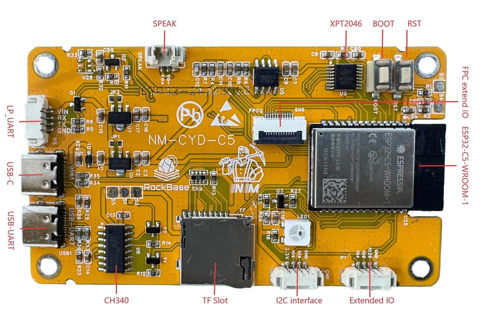
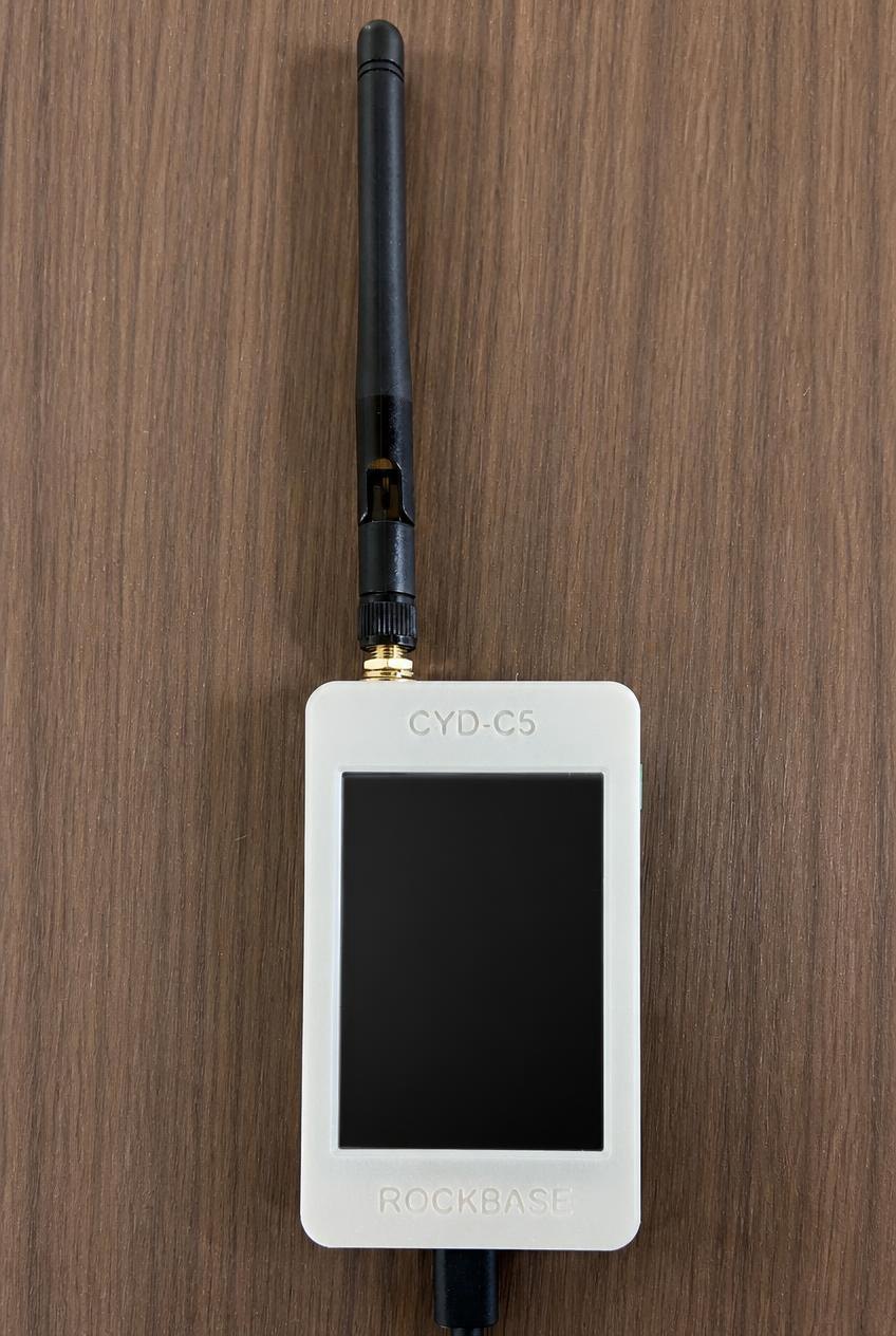
RockBase NM-CYD-C5. “The 2.8” CYD’s glass on an ESP32-C5, the first RISC-V chip here”: single-core RISC-V at 240 MHz, 2.4 + 5 GHz Wi-Fi 6, BLE 5.3, no Classic, 802.15.4, 16 MB flash, 8 MB PSRAM, backlight on GPIO 25 and a WS2812 on GPIO 27. It has two USB-C ports. The firmware’s console is on the CH340 port, and plugged into the native port the board “runs perfectly and prints nothing at all, which is indistinguishable from a board that failed to boot.” It builds on its own pioarduino platform (Arduino 3.3.12 / IDF 5.5.5) while every Xtensa board stays on [email protected]. 5 GHz scanning arrived in v1.31.0: after each 2.4 GHz sweep, a slice of at most 1.5 s covers recently busy 5 GHz channels plus two quiet ones, so 2.4 GHz keeps about three-quarters of the radio’s time.
Marauder V8 (justcallmekoko). ESP32-C5, 8 MB flash, 4 MB PSRAM, CP210x, ILI9341 2.8”, XPT2046, SD, a MAX17048 gauge (I²C 0x36) and GPS on GPIO 14 at 115200 baud. Its screen and touch pins “were found on the board (2026-10-12)” because Marauder’s own V8 display setup is not public. It wardrives to SD with a WiGLE file.
Freenove ESP32-S3 2.8” (FNK0104B). ESP32-S3R8 (8 MB octal PSRAM, 16 MB flash), ILI9341 at 40 MHz (“80 MHz garbles it”), FT6336 touch at I²C 0x38, 4-bit SDMMC, a WS2812 on GPIO 42, an ES8311 codec driving a speaker, and a battery on a 200K/200K divider into GPIO 9. “There is no fuel gauge, and the charger’s CHRG line drives an LED rather than a GPIO, so it cannot say ‘charging’.” Holding BOOT for three seconds powers it off.
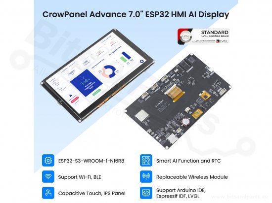
Elecrow CrowPanel Advance 7.0. ESP32-S3-WROOM-1-N16R8 behind an 800×480 RGB-parallel IPS panel. “Not a CYD: there is no SPI display bus at all.” The UI is drawn at 400×240 and doubled on purpose. It needs a 2 A supply because “the panel’s backlight plus WiFi joining a network browned a unit out on a laptop port.” Elecrow’s optional SX1262 LoRa module is where the project’s LoRa decoders were first developed and bench-tested.
LilyGo T-Deck Plus. ESP32-S3FN16R8 handheld with a 2.8” ST7789, GT911, an I²C keyboard, MAX98357A speaker, MIA-M10Q GPS, 2000 mAh cell and SX1262. LoRa was left out of v1.36.0 because the radio sharing the display bus cut the screen from 43 to 23 fps and crashed once on core 0.
M5Stack StickS3 and Cardputer ADV. Both use the 1.14” 135×240 ST7789 and no touch; a cursor stands in for a finger. The StickS3 (ESP32-S3-PICO-1-N8R8) uses two buttons; the Cardputer ADV (ESP32-S3FN8, no PSRAM) uses its 56-key TCA8418 keyboard (“Arrows and TAB move, ENTER presses, ESC goes home”) and has microSD. With 8 MB of flash, both take the CYDs’ two-slot partitions_ota.csv rather than the 16 MB table. These are the boards covered in the M5Stick S3 deep dive and the M5Stack Cardputer ADV deep dive.
2.7.4 The T-Watch S3 and S3 Plus in detail
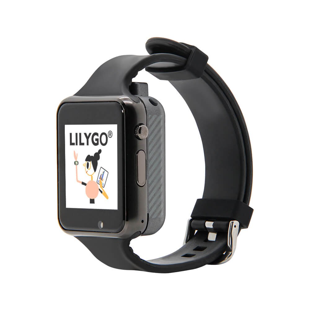
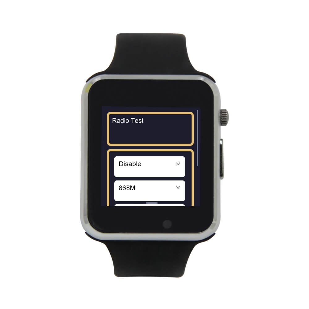
Table 11 — 7.4 The T-Watch S3 and S3 Plus in detail
| Item | T-Watch S3 | T-Watch S3 Plus |
|---|---|---|
| MCU | ESP32-S3, 16 MB flash, 8 MB OPI PSRAM | same |
| Display | 1.54” 240×240 ST7789, SPI (MOSI 13, SCLK 18, CS 12, DC 38), backlight GPIO 45 | same |
| Touch | FT6336 on I²C (SDA 39, SCL 40, INT 16) | same |
| Power chip | AXP2101 on a second I²C (SDA 10, SCL 11); must enable rails before display/touch answer | same; charge current raised to 400 mA |
| Haptics | DRV2605 on the power chip’s bus | same |
| LoRa | SX1262, receive only in SquachWatch | same |
| GPS | none (“the probe finds nothing, says so once”) | u-blox MIA-M10Q (LS550G on some batches), RX GPIO 41 / TX 42 |
| Cell | smaller | ”about twice the cell”; 3 h 18 min empty→94 % at 200 mA |
| SD / status light | none | none |
| Console | native USB, nominal 115200 | same |
Sources: include/twatch_s3_user_setup.h; src/main.cpp (twatchApplyCharge, DRV2605 and GPS sections); src/lora_radio.cpp; platformio.ini [env:twatch-s3]. LilyGo’s store lists the S3 Plus with a 940 mAh battery. There is one firmware for both watches: the Plus is detected at runtime. The crown is the only wake button in POCKET MODE, POWER SAVER is on by default, and TAGS + RINGS defaults to LOG ONLY so passing AirTags do not buzz the wrist all day. Vol 9 covers LoRa and wardriving.
2.7.5 Choosing among them
  Which board? (hardware view)
  ─────────────────────────────────────────────────────────────────────
  Need it to "just work" today, cheapest ──────► 2.8" CYD (cyd / cyd-ili9341)
  Want capacitive touch, no BETA label ────────► 3.2" ESP32-2432S032C (cyd32c)
  Want a battery with no wiring ───────────────► RL Phantom pre-built,
                                                 or Freenove S3 2.8" + LiPo (BETA)
  Want 5 GHz ──────────────────────────────────► NM-CYD-C5 (BETA) / Marauder V8 (BETA)
  Want GPS wardriving ─────────────────────────► T-Watch S3 Plus / Marauder V8 /
                                                 T-Deck Plus (all BETA);
                                                 or cyd-gps from source
  Want LoRa (Meshtastic/MeshCore listening) ───► T-Watch S3 or S3 Plus
  Avoid unless prepared to debug ──────────────► 3.5" ESP32-3248S035R (boot loops)
2.8 Cheatsheet updates from this volume
Table 12 — 8. Cheatsheet updates from this volume
| Fact | Value |
|---|---|
| CYD MCU | ESP32-WROOM-32, dual LX6 240 MHz, 520 KB SRAM, no PSRAM, 4 MB flash |
| Display builds | cyd (ST7789, BGR) / cyd-ili9341 (ILI9341, RGB); white screen → other build |
| Display pins | MOSI 13, MISO 12, SCLK 14, CS 15, DC 2, BL 21 |
| Touch pins | CS 33, IRQ 36, MOSI 32, MISO 39, SCLK 25 |
| SD pins | CS 5, MOSI 23, MISO 19, SCLK 18; FAT32 |
| Status light | R 4 / G 16 / B 17, common anode, LOW = on |
| Spare GPIO | 22, 35 (input-only), 27 (driven high at boot) |
| Console | 2,000,000 baud on CH340 CYDs; 115200 on S3/C5 boards |
| Power | 5 V only on the classic CYD; no battery or gauge |
| 80 MHz | ~34 fps vs ~22 fps at 40 MHz; overclock, reversible by reflash |
| Never | flash a merged image at 0x0 by hand: it erases NVS |
| 5 GHz boards | NM-CYD-C5, Marauder V8 |
| LoRa/GPS | T-Watch S3 (LoRa), S3 Plus (LoRa + GPS) |
Comments (0)