HaleHound · Volume 6
HaleHound Volume 6 — Full Build: Fire Weasel
The integrated radio board and leash — a ~45-minute build, plus the shared power section every HaleHound needs
6.1 About this Volume
This volume builds the Fire Weasel — HaleHound’s integrated-board path, where the external radios and their power regulation live on one PCB that connects to the CYD through a short flexible “leash.” It is the faster of the two build paths: the vendor puts a Fire Weasel DIY kit at about 45 minutes with experience, against the two-to-three hours of the Classic hand-wired carrier build (Vol 5). The firmware and capabilities are identical between the two paths; only the physical assembly differs.
Because power is the same problem on either path — a 1S LiPo, a boost converter to make the 5 V the CYD expects, and the independent buck the amplified PA modules need — this volume also carries the shared power section (§7) that both build paths reference.
The electrical reference for every radio pin is Vol 3 (The Radios); the Classic hand-wired walkthrough is Vol 5. This volume leans on both: it says what the Fire Weasel board does for you (so you do not wire it) and what you still have to do yourself (the leash, the GPS lead, the power, the battery, the firmware, and the antennas).
Warning — Authorized use only. A completed Fire Weasel is a full-power multi-band transmitter with amplified sub-GHz and 2.4 GHz front ends. Everything here assumes operation only on hardware and spectrum you own or are explicitly authorized to test, under the posture of Vol 9 and
../_shared/legal_ethics.md.
6.2 What the Fire Weasel is
The Fire Weasel is a purpose-built carrier that integrates what the Classic build assembles from a Cinder Ferret plus a hand-run harness. On one board it carries the amplified sub-GHz and 2.4 GHz radios (the E07 CC1101-with-PA and the E01 NRF24-with-PA), the power regulation those PA modules require, and the pads and connectors for the battery, the GPS lead and the leash to the CYD.
   ┌─────────────────────────────┐    leash     ┌────────────────────┐
   │   FIRE WEASEL BOARD          │◄──(signal)──►│  4" exposed-SPI CYD │
   │                              │              │  (E32R40T, ST7796   │
   │  ┌────────┐  ┌────────┐      │              │   320×480 class)    │
   │  │E07 PA  │  │E01 PA  │      │              │                     │
   │  │sub-GHz │  │2.4 GHz │      │              │  VSPI + reclaimed   │
   │  └────────┘  └────────┘      │              │  GPIOs + P1 serial  │
   │  [boost] [3.3V buck]         │              └────────────────────┘
   │  BAT+ / BAT−  (above blue)   │
   │  GPS 4-pin UART header       │────► ATGM336H GPS (ceramic antenna)
   └─────────────────────────────┘
Figure 6.1 — The Fire Weasel integrates the radios, the boost converter and the PA buck on one board; a short leash carries the signal lines to the CYD, and the battery solders to the BAT pads.
It is a community design. The vendor credits it as “Designed by Midwest Gadgets, inspired by BkBroiler … in conjunction with Hamspice” — the same community that shaped the firmware’s OPSEC. The intent stated on the store is explicit: “this clever little monster brings accessibility to even more folks than before” — i.e. it lowers the soldering bar relative to a Classic Cinder Ferret build.
The structural reason it is faster is worth stating plainly: a Classic build’s difficulty is almost entirely the harness in Vol 5 §8 — a dozen-plus individual signal lines, each landed on a specific reclaimed GPIO, each a chance to swap a pin or cold-joint a wire. The Fire Weasel moves all of that onto a PCB and a single pluggable leash. What is left for the builder is the handful of jobs that are inherently yours — your battery, your antennas, your flashing — plus seating the leash and the GPS lead. Fewer hand-made joints means fewer faults and a shorter build, at the cost of some per-wire repairability (you replace a leash, not re-run a wire).
The Fire Weasel is sold several ways, which is worth knowing before buying:
Table 1 — The Fire Weasel is sold several ways, which is worth knowing before buying
| SKU (2026-10-16) | ~Price | What it is |
|---|---|---|
| Fire Weasel 4” DIY kit | ~$198 | Full build: board, leash, 4” CYD, E07, E01, GPS, boost, buck, case, hardware |
| Fire Weasel + leash PRO DIY | ~$185 | The pro leash variant of the DIY path |
| Fire Weasel board + leash DIY (un-soldered) | ~$48 | Just the board and leash, you solder |
| Fire Weasel board + leash (soldered & assembled) | ~$78 | Board pre-soldered and tested, plus leash |
| Weasel leash replacement | ~$8 | A spare leash — they are a wear item |
| Fire Weasel “bone pile” case | ~$45 | The case redone for the Fire Weasel board |
  Fire Weasel entry points — approximate cost (USD, 2026-10-16)
  Board+leash (un-soldered)  ████████ $48
  Board+leash (assembled)    ████████████ $78
  + leash PRO DIY            ██████████████████████████████ $185
  Full 4" DIY kit            ████████████████████████████████ $198
                             0    40    80   120   160   200
Figure 6.2 — The Fire Weasel is sold from a bare board-and-leash up to a complete 4” DIY kit. The two low-cost SKUs assume you already have a CYD and the rest of the parts; the full kit is the from-nothing path. Add antennas and a battery to any of them.
The amplified-by-default point matters for the buy decision: the Fire Weasel full kit ships the E07 (amplified sub-GHz) and E01 (amplified 2.4 GHz) PA modules, where a baseline Classic build can start on the stock HW-863 CC1101 and a plain NRF24. That is real capability — the E07 raises CC1101 TX from ~+12 dBm to ~+20 dBm (Vol 3 §10) — but it is also why the Fire Weasel needs the independent buck (§7.3) that comes in the kit. You are buying the amplified front ends and the power plumbing to feed them, together.
6.3 Kit contents
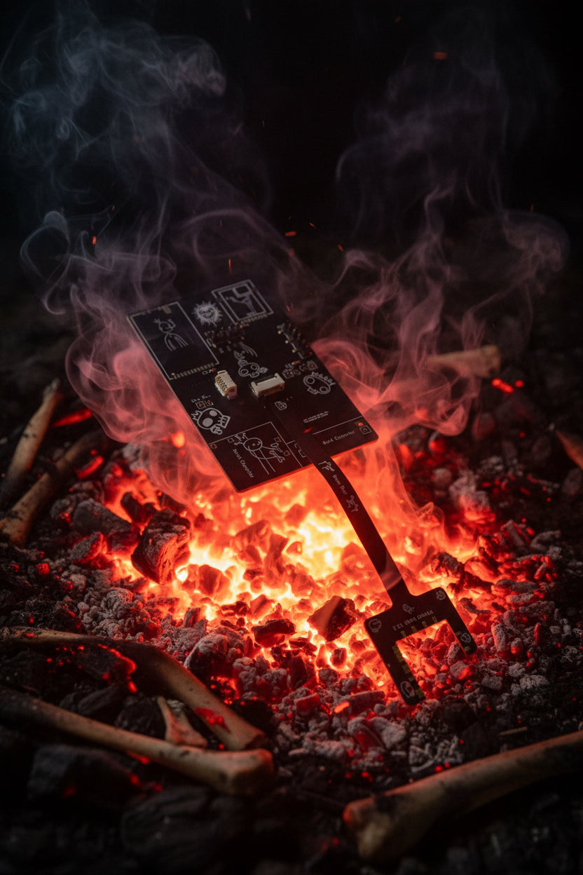
Figure 6.3 — The Fire Weasel board and leash. The leash is the short flexible link that carries signal lines from the board to the CYD’s exposed-SPI pins. Photo: HaleHound.com.
The 4” DIY Fire Weasel kit ships the following (vendor-listed):
Table 2 — The 4" DIY Fire Weasel kit ships the following (vendor-listed)
| # | Item | Notes |
|---|---|---|
| 1 | HaleHound 3D-printed case | The “bone pile” Fire Weasel case |
| 2 | Fire Weasel board | Integrated radio + power carrier |
| 3 | Fire Weasel leash | Board ↔ CYD signal link |
| 4 | 4” E32R40T exposed-SPI CYD | ST7796-class 320×480 touch display |
| 5 | E07 — CC1101 sub-GHz radio | Amplified (20 dBm) sub-GHz PA module |
| 6 | E01 — NRF24 2.4 GHz radio | Amplified (27 dBm-class) 2.4 GHz PA module |
| 7 | Generic 4-pin wiring harness | GPS, delivered over UART |
| 8 | ATGM336H GPS + ceramic antenna | 9600-baud NMEA receiver |
| 9 | Boost converter module | Voltage step-up (LiPo → 5 V) |
| 10 | 3.3 V buck converter | Voltage step-down (independent PA supply) |
| 11 | M3 × 10 case hardware | Mounting screws |
Not in the kit: battery, antennas, PN532 NFC/RFID module, firmware, solder, and tools. The kit deliberately includes both power converters — the boost (to make 5 V from the cell) and the buck (the independent 3.3 V the E07/E01 PAs demand, per Vol 3 §8) — which is one reason the Fire Weasel is simpler than sourcing a Classic PA build, where the buck is a source-it-yourself item.
Note — The 4” board’s build target. The kit ships a 4” E32R40T exposed-SPI CYD. The HaleHound complete 4” unit is documented on the QDtech 4” ST7796U 320×480 panel — the same controller family as the E32R35T 3.5” board — so the firmware’s 320×480 ST7796 build (the
esp32-e32r35t-class target) is what drives it, and the web flasher’s board finder selects it. Confirm the exact board code in the flasher before flashing.
6.4 Pre-wired vs what you do
The whole value of the Fire Weasel is that the radio-to-radio and radio-to-power wiring is done on the board. Being precise about the boundary keeps the build fast:
Table 3 — done on the board. Being precise about the boundary keeps the build fast
| Done for you (on the board) | What you do |
|---|---|
| E07 + E01 mounted and routed | Attach the leash to the board and the CYD |
| PA power regulation (buck) placed | Wire the boost/battery power path (§7) |
| Radio signal lines to the leash header | Connect the GPS 4-pin lead |
| BAT+/BAT− pads provided | Solder the battery leads to BAT+/BAT− |
| Antenna SMA positions | Fit your own antennas (§8) |
| — | Flash the firmware (Vol 7) |
| — | Assemble into the case with M3 hardware |
The jobs that remain are deliberately the few that cannot be pre-done: the ones specific to your battery, your antennas, and your flashing. Everything that is a fixed electrical fact — which PA pin goes to which GPIO, where the buck feeds — is already on the PCB.
Tip — Buy it pre-soldered if you want the floor even lower. The board-and-leash SKU comes in a “Fully Soldered & Assembled” variant (~$78 vs ~$48 un-soldered). With a pre-soldered board the remaining work is essentially the leash, the GPS lead, the power and the battery — which is how the ~45-minute figure is reached.
6.5 The leash
Figure 6.4 — The leash carries the radio signal lines from the Fire Weasel board to the CYD’s exposed-SPI pins. Photo: HaleHound.com.
The “leash” is the short flexible connector that carries the signal bus between the Fire Weasel board and the CYD. Electrically it is the Fire Weasel’s equivalent of the Classic build’s hand-run harness (Vol 5 §8) — it lands the shared VSPI lines (GPIO 18/19/23), the chip-selects and control lines on the CYD’s exposed-SPI pins. Mechanically it is a flex link that lets the two boards fold into the case.
Two practical points:
- It is a wear item. HaleHound sells a leash replacement (~$8) precisely because a flex link that is folded and unfolded will eventually fatigue. If a built unit develops intermittent radio faults after use — radios that drop out when the case is flexed — suspect the leash before the board.
- The “PRO” leash is the upgraded variant sold with the Fire Weasel + leash PRO DIY kit. It is the same electrical function in a more durable form.
Seat the leash squarely at both ends and confirm it is fully home before powering up — a half-seated leash presents exactly like a bad harness joint on a Classic build: several radios failing at once because the shared bus is interrupted (Vol 3 §2).
6.5.1 What the leash carries
Electrically the leash lands the same signal set a Classic harness lands by hand (Vol 5 §8), onto the CYD’s exposed-SPI pins. Because the 4” kit board is an ST7796 320×480-class panel, it uses the 3.5”/E32R35T pin assignments (Vol 3 §9), not the base 2.8” ones — the two chip-selects that move are the point to notice:
Table 4 — chip-selects that move are the point to notice
| Signal | Pin on the 4”/320×480 CYD | Note |
|---|---|---|
| VSPI SCK / MISO / MOSI | GPIO 18 / 19 / 23 | Shared bus, also the SD card |
| CC1101 (E07) CS | GPIO 21 | Not 27 — backlight owns 27 on this panel |
| CC1101 GDO0 (TX) / GDO2 (RX) | GPIO 22 / 35 | GDO0=TX, GDO2=RX (Vol 3 §4.2) |
| NRF24 (E01) CSN | GPIO 26 | Not 4 — GPIO 4 is the E07 PA TX_EN |
| NRF24 CE / IRQ | GPIO 16 / 17 | IRQ optional |
| E07 PA TX_EN / RX_EN | GPIO 4 / 0 | PA path enables |
| GPS TX in | GPIO 1 (P1 “TX”) | On its own UART, not the leash bus |
The builder does not route any of this on a Fire Weasel — the board and leash already carry it. The table is here so that a fault can be reasoned about against real pins, and so a Classic-build reader can see that the two paths land the identical signals; only the delivery differs (hand-run harness vs a one-piece leash).
6.6 The build, step by step (~45 min)
The sequence below assumes the DIY kit and a board you will solder yourself; skip the board soldering steps if you bought the pre-soldered variant. Keep the battery off the bench until §7 — solder everything and test on USB first.
- Inventory the kit against §3. Confirm both power converters (boost and buck) are present and that you can tell them apart — the boost steps the cell up to 5 V, the buck steps down to the PA’s 3.3 V. Mixing them up is the one error that can damage a radio.
- Solder the board (un-soldered kits): seat and solder the E07 and E01 and the power converters in their marked positions. The board does the routing; you are just populating footprints.
- Attach the leash to the Fire Weasel board, then to the CYD’s exposed-SPI pins. Seat it fully at both ends (§5).
- Connect the GPS via the 4-pin UART lead to the board’s GPS header; route the ATGM336H and its ceramic antenna toward a clear-sky exit in the case. The GPS lands on the CYD’s P1 serial pins and shares UART0 with USB — the firmware handles that (Vol 3 §7.2).
- Wire the power path (§7): the boost converter output feeds the CYD’s 5 V; the battery feeds the boost. Do not connect the battery yet.
- Verify the buck output with a meter before trusting it: it must read 3.3 V for the PA modules, not 5 V (§7, Vol 3 §8). Do this with the PAs not yet drawing, if the board layout allows isolating it.
- Fit antennas (§8) — both SMA positions — before any transmit.
- Flash the firmware (Vol 7) at flash.halehound.com, Chrome/Edge, correct build target.
- First boot: touch-calibrate (tap the four corners), fix rotation if needed (Settings → Rotation).
- Run Tools → Radio Test and confirm every radio reads OK (§9). The firmware carries 4-page wiring diagrams here, the same as reproduced in Vol 3.
- Solder the battery to BAT+/BAT− (§7) only after every radio passes on USB power.
- Assemble into the case with the M3 × 10 hardware; re-run Radio Test after closing.
   Fire Weasel build order
   solder board → leash → GPS → power path → verify buck 3.3V
     → antennas → flash → Radio Test (USB) → battery → case
Figure 6.5 — The build order. Battery last, antennas before transmit, Radio Test on USB before the battery goes on — the same safety ordering as the Classic build.
6.6.1 The GPS lead and the generic UART harness
Kit item 7 is a “generic wiring harness with 4 pin to deliver via UART” — this is the GPS link, and it is the one radio connection that is not on the leash’s SPI bus. The ATGM336H (kit item 8) is a plain 9600-baud NMEA receiver; its data reaches the ESP32 over a UART, not SPI (Vol 3 §7). The four pins are VCC, GND, the module’s TX (to the CYD’s P1 “TX” = GPIO 1), and the module’s RX (unused — the GPS is receive-only).
Two things to get right on this lead:
- Orientation. The module’s TX must reach the CYD’s TX pin on P1 — that pin is GPIO 1. This looks like a TX-to-TX “mistake” but it is correct for how the P1 header is labelled; follow the Vol 3 §7.1 table.
- No USB serial while GPS runs. GPIO 1 is the USB-serial UART0 line; the firmware detaches
it (
Serial.end()) while a GPS mode is active and restores it on exit. Expect no console output during wardriving — that is designed behaviour, not a fault (Vol 3 §7.2).
Route the ceramic patch antenna toward a clear-sky exit; a GPS buried behind the battery or the PA modules will struggle to lock.
6.6.2 Soldering notes specific to this board
- Tell the boost from the buck before you place either. They look similar; the boost steps the cell up to 5 V, the buck steps down to the PA’s 3.3 V. Swapping them is the one assembly error that can put 5 V onto a 3.3 V radio. Confirm the silk and the module markings against §7 before soldering (kit item 9 = boost, item 10 = buck).
- Seat the PA modules flat. The E07 and E01 sit in their footprints; a lifted module stresses the SMA and the joints when the case closes.
- Tin the BAT pads but leave the battery off until §9. There is no reason for a charged LiPo to be near the iron during assembly.
6.7 Power — the shared section
This section is referenced by both build paths. Every HaleHound, Classic or Fire Weasel, has the same three power problems to solve: make the 5 V the CYD wants from a single LiPo cell, feed the PA modules their own clean 3.3 V, and attach the battery safely.
6.7.1 The cell: 1S LiPo
The recommended battery is a 3.7 V 1S LiPo; the vendor specifically recommends a 5000 mAh cell for the 4” builds (listing a 105080-class pack). A 1S cell nominal 3.7 V sits below the 5 V the CYD’s input expects, which is why a boost converter is mandatory for battery operation — the cell cannot feed the board directly.
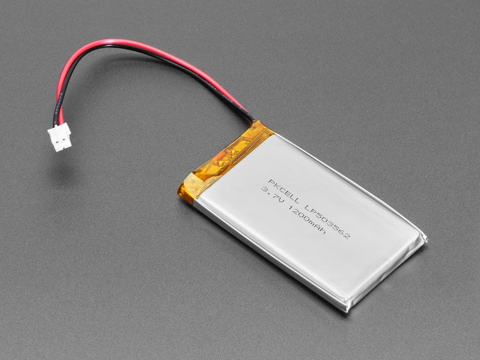
Figure 6.6 — A 1S LiPo of the type the build uses; size the real cell to the case. Photo: representative LiPo (Adafruit).
6.7.2 The boost converter (cell → 5 V)
The boost converter steps the ~3.7 V cell up to the 5 V the CYD’s input rail expects. On the Fire Weasel it is the kit-supplied boost module; on a Classic build it is a maker-pattern boost (MT3608-class) or a combined charger/boost board. The pattern:
   1S LiPo (3.7V nominal)
        │
        ▼
   BOOST converter ──► 5V ──► CYD 5V input
   (step-up to 5.0V)          (then the CYD's own LDOs → ESP32 + TFT)
        │
   (charge the cell via a charger stage / USB when not in use)
Figure 6.7 — The boost path: the 1S cell is stepped up to 5 V to feed the CYD. A charger stage (or USB) tops the cell up.
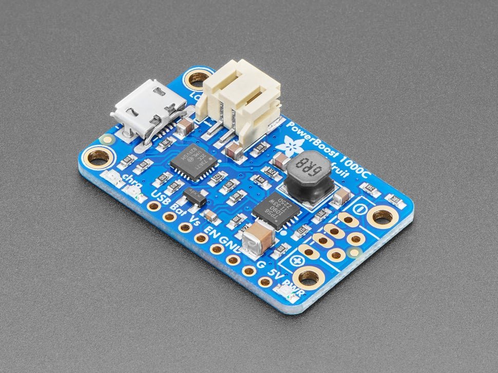
Figure 6.8 — A charger/boost board of the class used to power a CYD from one cell. Photo: representative boost/charger (Adafruit).
6.7.3 The PA buck (independent 3.3 V)
The amplified E07 and E01 modules draw a current transient the CYD’s small LDOs cannot source, so they get their own 5 V → 3.3 V buck — the kit-supplied one on a Fire Weasel, or an AMS1117-3.3 / MP2307 (≥500 mA) on a Classic PA build. This is the Vol 3 §8 rule, restated because it is the most common field-failure cause:
- Input: 5 V (from the boost / USB VBUS).
- Output: 3.3 V to the PA modules’ VCC only — verified with a meter before connecting.
- Signal lines still go to the ESP32 GPIO; only VCC comes from the buck.
- All grounds common — buck, CYD, modules.
On the Fire Weasel this buck is on the board and pre-routed; on a Classic build you wire it. Either way, meter 3.3 V before you trust it.
6.7.4 Runtime — an order-of-magnitude estimate
No measured battery life is published, so this is an engineering estimate, not a spec. The inputs: a recommended 5000 mAh 1S cell (~3.7 V, so roughly 18.5 Wh of stored energy), a CYD with a bright TFT backlight, and radios that transmit at full power when active. Treating the boost + LDO chain as ~85% efficient:
Table 5 — boost + LDO chain as ~85% efficient
| Load scenario | Rough draw | Estimated runtime from 5000 mAh |
|---|---|---|
| Idle / menu, backlight dimmed | ~150–250 mA | ~15–25 h |
| Scanning / receive, screen on | ~300–450 mA | ~8–13 h |
| Sustained PA transmit (E07/E01 keyed) | ~600 mA–1 A+ | ~3–6 h |
Table — Order-of-magnitude only. Real figures depend on backlight (Settings → Brightness), screen-timeout, which radios are active, and antenna match. Treat these as a planning range, not a datasheet.
The practical levers a field operator has: drop the backlight (Settings → Brightness, PWM 10–255), set a short screen timeout (Settings → Screen Timeout), and avoid leaving a PA keyed in a carrier/flood mode longer than needed. The 5000 mAh cell is recommended specifically because the 4” screen and the amplified front ends are both hungry; a smaller cell will work but shortens every row above.
6.7.5 The battery pads — solder, do not plug
This is the power step most often done wrong. On the Fire Weasel (and the complete units) the battery leads are soldered to the BAT+ / BAT− pads — on the Fire Weasel board these are above the blue module. The connector on the cell does not plug into the board:
Warning — The battery solders to the pads; the cell’s connector does not plug in. The vendor is emphatic about this across the listings: “The battery leads get SOLDERED to the BAT+ / BAT− pads … the connector on the cell does NOT plug into this board.” Cut or ignore the cell’s JST connector and solder the leads to the pads, observing polarity.
LiPo safety that is not optional:
- Observe polarity. BAT+ to +, BAT− to −. A reversed LiPo is a destroyed board at best.
- Never solder to a connected/charged cell under tension. Tin the pads first, then join.
- Use a protected cell and never leave an unprotected pouch charging unattended.
- Battery goes on last, after every radio passes Radio Test on USB power (§6, §9).
   Fire Weasel power summary
   ┌──────────────────────────────────────────────┐
   │  1S LiPo ──► BOOST ──► 5V ──► CYD (LDOs→3.3V)   │
   │                 │                              │
   │                 └──► BUCK ──► 3.3V ──► E07/E01 │
   │  BAT+/BAT− pads (above blue module): SOLDER     │
   │  ALL GROUNDS COMMON                             │
   └──────────────────────────────────────────────┘
Figure 6.9 — The complete power picture: one cell, boosted to 5 V for the CYD, bucked to 3.3 V for the PAs, soldered at the BAT pads, everything grounded together.
6.8 Antennas
No HaleHound SKU ships antennas — the vendor’s position is that everyone has a preferred antenna. The store’s own recommendations:
Table 6 — antenna. The store's own recommendations
| Band | Recommended antenna | Fits |
|---|---|---|
| 2.4 GHz (NRF24/Wi-Fi) | Bolton Dart | E01 SMA |
| Sub-GHz (CC1101) | ANT700 telescopic whip | E07 SMA |
Any resonant 433/315 MHz whip works for sub-GHz and any 2.4 GHz dipole/SMA antenna works for the 2.4 GHz front end. The ESP32’s own Wi-Fi/BLE uses the CYD’s PCB trace antenna and has no connector — only the E07 and E01 PA front ends terminate in SMA.
Warning — Antennas before PA transmit. A 20 dBm PA keyed into an open SMA can reflect enough power to damage its final stage. Fit both antennas before enabling PA mode or transmitting (Vol 3 §8.3).
6.9 First-power checklist
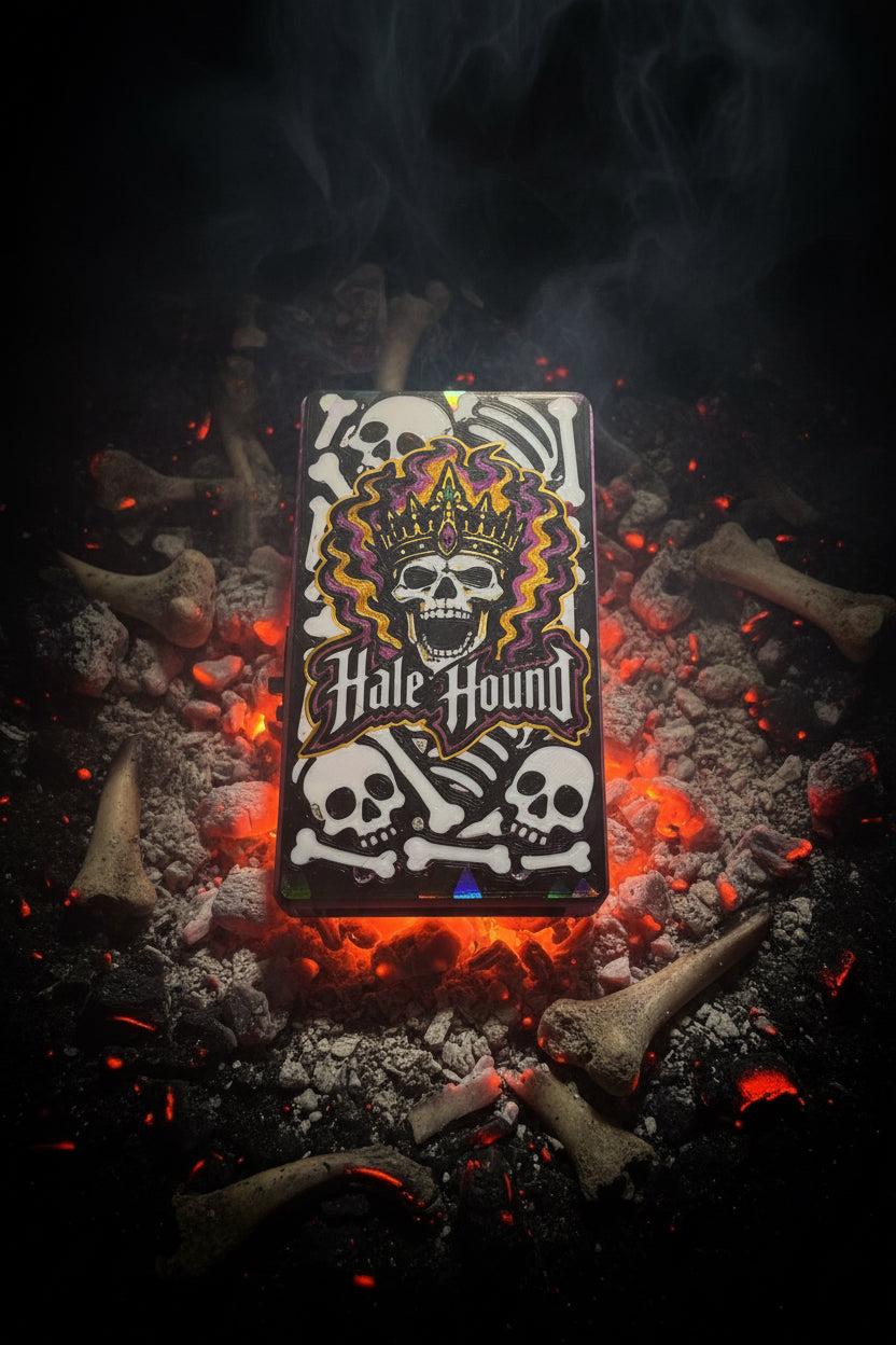
Figure 6.10 — The Fire Weasel “bone pile” case. The build closes into this with the M3 × 10 hardware. Photo: HaleHound.com.
Run this before trusting the unit in the field:
   Fire Weasel first-power checklist
   ┌─────────────────────────────────────────────────┐
   │ [ ] Leash fully seated both ends                   │
   │ [ ] GPS 4-pin lead connected                       │
   │ [ ] Buck meters 3.3 V (not 5 V) before PA draws    │
   │ [ ] Boost output 5.0 V to CYD                      │
   │ [ ] Antennas fitted (both SMA)                     │
   │ [ ] USB power only — no battery yet                │
   │ [ ] Display boots, touch + rotation calibrated      │
   │ [ ] Radio Test: CC1101 / NRF24 / (PN532) / GPS OK  │
   │ [ ] GPS locks outdoors                             │
   │ [ ] THEN solder battery to BAT+/BAT−               │
   │ [ ] Case closed; Radio Test re-run and still green │
   └─────────────────────────────────────────────────┘
Figure 6.11 — The acceptance gate. Battery and case come after a clean Radio Test on USB.
If the PN532 is fitted (it is not in the kit — source it separately and set its DIP switches CH1 OFF / CH2 ON, Vol 3 §6.2), it appears in Radio Test too; without it, the NFC menu simply offers its BLE Chameleon Ultra and stub back ends instead.
6.9.1 Adding the PN532 later
Because the kit omits the PN532, NFC is a common after-the-fact addition on a Fire Weasel. It lands on the shared VSPI bus like the other SPI radios, with its SS on GPIO 17 (Vol 3 §6). The two things that trip people adding it late:
- The DIP switches must be CH1 OFF / CH2 ON for SPI mode before it will answer — it defaults to I²C or HSU out of the bag and is silent on SPI until switched (Vol 3 §6.2).
- GPIO 17 is shared with the NRF24 IRQ. The NRF24 IRQ is optional and should be left unconnected so the PN532 SS owns GPIO 17 (Vol 3 §9). On a Fire Weasel the board already arranges this; if you are hand-landing a PN532 onto the leash’s spare, leave the NRF24 IRQ open.
A Chameleon Ultra over BLE is the no-solder NFC alternative — the firmware drives one as a back end for NTAG work and mfkey32 recovery (see the Chameleon Ultra deep dive and Vol 11), at the cost of carrying a second device.
6.10 Field-readiness and maintenance
Passing Radio Test on the bench is necessary but not the whole picture; a HaleHound that lives in a bag and gets flexed has a few wear points worth a periodic check.
Table 7 — 10. Field-readiness and maintenance
| Item | Check | When |
|---|---|---|
| Leash | Re-seat; look for crease fatigue at the folds | Monthly, or after any intermittent-radio symptom |
| BAT pads | Inspect solder joints for strain/cracking | After a drop or a case open |
| microSD | Confirm present and FAT32; back up loot | Before and after an engagement |
| Firmware | Latest build via OTA from SD /firmware/ or re-web-flash | Per release (v4.0 released 2026-10-15) |
| Antennas | SMA finger-tight; never transmit on an open port | Every power-up before PA use |
| Buck output | Spot-meter 3.3 V if a PA starts browning out | On any new reset symptom |
The firmware update path is covered in Vol 7 — OTA drops a .bin into the SD /firmware/
folder and the device flashes itself (Tools → Update Firmware), or the unit can be re-flashed
from flash.halehound.com at any time. Keep a known-good .bin on the card as a field recovery
option.
Tip — The leash is the most likely field failure. A flex connector folded into a case and carried for months is the part that fatigues first. Carry a spare (~$8) for any serious field use; swapping it is faster than diagnosing it.
6.11 Differences from the Classic build
Both paths run the identical firmware and reach the same Radio-Test-green unit. The differences are entirely mechanical and in what the kit solves for you:
Table 8 — differences are entirely mechanical and in what the kit solves for you
| Dimension | Classic (Vol 5) | Fire Weasel (this volume) |
|---|---|---|
| Radio mounting | Cinder Ferret carrier, hand-seated | Integrated on the Fire Weasel board |
| Inter-board wiring | Full signal harness, hand-run | Pre-wired; a leash links board ↔ CYD |
| Independent PA buck | Source and wire it yourself | Supplied in the kit, pre-routed |
| Boost converter | Source it (maker pattern) | Supplied in the kit |
| Typical build time | ~2.5–3 h first build | ~45 min with experience |
| Default radios | Stock HW-863 / plain NRF24 (PA optional) | Amplified E07 + E01 by default |
| Cheapest entry | ~$139 DIY 2.8” kit | ~$198 DIY 4” kit |
| Repairability | At the wire — easy to trace/fix | Board-level; leash is the serviceable part |
| Best for | Cost, control, learning the wiring | Speed, fewest wiring mistakes |
The honest summary: the Classic build is cheaper and teaches the platform at the wire level; the Fire Weasel trades roughly $60 and some repairability for a build that is hard to get wrong and genuinely fits in under an hour. Both are the same device once Radio Test is green.
6.12 Troubleshooting a Fire Weasel build
Because so much is pre-wired, Fire Weasel faults cluster around the few things you did yourself: the leash, the power path, the battery, and the antennas. This is the diagnostic advantage of the integrated build — the fault surface is small and well-defined, where a Classic build can fail at any one of a dozen hand-landed signal wires. Work the table top-down; if a fix is not obvious, the fastest triage is almost always to re-seat (or swap) the leash and re-run Radio Test on USB power before opening anything else.
Table 9 — 12. Troubleshooting a Fire Weasel build
| Symptom | Likely cause | Fix |
|---|---|---|
| Several radios fail Radio Test at once | Leash not fully seated | Re-seat the leash both ends (§5) |
| Radios drop out when the case flexes | Leash fatigue | Replace the leash (~$8 wear item, §5) |
| Brown-out / resets when a PA keys | Buck not at 3.3 V, or shared rail | Meter buck = 3.3 V; PA VCC only from buck (§7.3) |
| Board dead on battery, fine on USB | BAT pad polarity / cold joint | Re-check BAT+/BAT− solder and polarity (§7.5) |
| Nothing powers from the cell | Boost not making 5 V | Meter the boost output; set/replace it (§7.2) |
| GPS never locks | Lead not seated / no sky view | Re-seat the GPS 4-pin lead; test outdoors (§6) |
| Display upside-down / touch off after flash | Normal first-boot | Settings → Rotation; re-tap calibration (Vol 7) |
| PA final stage damaged / weak TX | Keyed PA into an open SMA | Always fit antennas before transmit (§8) |
| A radio smells hot on first power | Boost/buck swapped, or short | Pull power immediately; confirm boost vs buck (§6 step 1) |
Tip — Isolate the leash first. The Fire Weasel’s single biggest difference from a Classic build, diagnostically, is that its “harness” is one replaceable part. If multiple radios misbehave, re-seat or swap the leash before opening up anything else — it is the cheapest and most likely fix.
With a clean first-power checklist (§9) and Radio Test green with the case closed, the Fire Weasel is ready for flashing follow-ups (OTA, SD layout — Vol 7, Vol 8), the capability tour (Vol 8), and field use under the authorization boundary of Vol 9. It is the same device as a Classic build — reached in about a third of the time.
Comments (0)