LakeShark · Volume 3
LakeShark Volume 3 — SDR Theory & the USB-Host Miracle
How xtrsdr adapts librtlsdr onto the ESP-IDF USB host stack, why High-Speed USB unlocks 2 MSPS, what the RTL2832U + R820T2 front end actually does, and the experimental HackRF transport
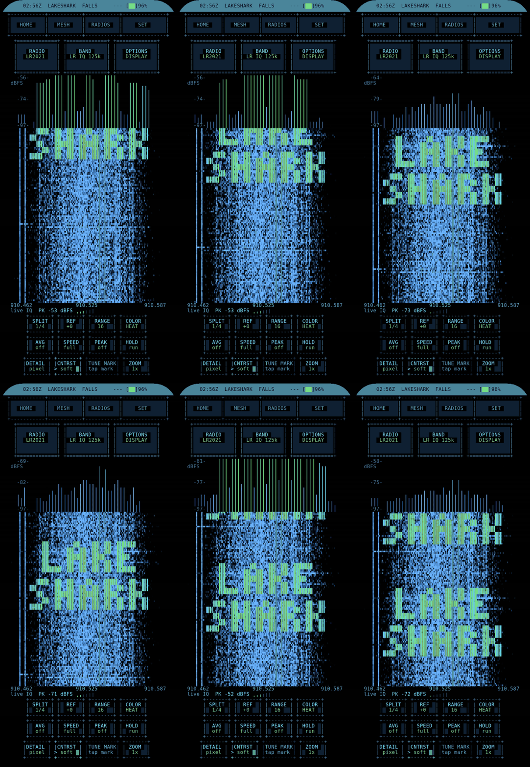
3.1 About this Volume
Volume 2 ended on a claim: the ESP32-P4’s High-Speed USB host is the one feature that makes a host-free SDR scanner possible. This volume makes good on that claim. It is the signal-path and software story of how a $30 RTL-SDR dongle, designed to talk to a PC, comes to be driven directly by a microcontroller at its full sample rate — and what the dongle is actually doing to the RF before the first line of on-device DSP (which Volume 4 then picks up).
The spine of the explanation is a single open-source project: XTR1984/xtrsdr, an “ESP32-optimized librtlsdr” that adapts the Osmocom librtlsdr driver onto the ESP-IDF USB host stack. Understanding that adaptation — and the USB bandwidth arithmetic behind it — is understanding why LakeShark is a 2026 project and not a 2020 one. The volume assumes familiarity with sampling, mixing, and quadrature IQ at the level any SDR practitioner has; it does not re-teach the Nyquist theorem, but it does connect it precisely to the numbers that matter here.
3.2 What an RTL-SDR is, in one page
The RTL-SDR began as a DVB-T television tuner dongle. Realtek’s RTL2832U demodulator chip has a debug mode that streams raw ADC samples over USB instead of demodulating broadcast TV, and the community turned that mode into the cheapest general-purpose software-defined radio in existence. A modern RTL-SDR Blog V3 or V4 pairs the RTL2832U with a Rafael Micro R820T2 tuner (V4 uses an R828D in a slightly different arrangement), giving continuous coverage from roughly 24 MHz to 1.7 GHz, 8-bit IQ samples, and sample rates up to about 3.2 MSPS (2.4 MSPS reliable; 2.0 MSPS the practical sweet spot).
The dongle does not decode anything. It is a tunable window onto the spectrum: set a centre frequency and a sample rate, and it returns a stream of complex (I, Q) samples representing the RF in a band of width equal to the sample rate, centred on the tuned frequency. Every decode LakeShark performs — P25, FM, ADS-B, POCSAG — is software applied to that IQ stream after it leaves the dongle. The dongle’s job ends at “here is the spectrum as numbers.”
3.2.1 Why the samples are complex
The “I and Q” pair is not an implementation curiosity; it is what lets a receiver represent both sides of the tuned frequency without ambiguity. A single real-valued sample stream cannot distinguish a signal 50 kHz above the centre from one 50 kHz below it — the two fold onto each other. Quadrature sampling (in-phase I and quadrature Q, 90° apart) carries the sign of the offset, so the full span from centre − R/2 to centre + R/2 is unambiguous. This is why a complex stream at rate R represents R Hz of spectrum rather than the R/2 a real stream would, and it is the reason the byte-rate arithmetic of §4 uses two bytes per sample. Every stage downstream — the FM discriminator, the C4FM slicer, the Mode S correlator — assumes complex input, which is exactly what the RTL2832U delivers.
3.3 The RTL2832U + R820T2 front end
Walking the signal from antenna to IQ makes clear what the dongle contributes and where its limits are.
 antenna ──▶ R820T2 tuner ──▶ RTL2832U ──────────▶ USB bulk ──▶ ESP32-P4
 (RF front end) (ADC + I/Q (8-bit I/Q (xtrsdr)
 decimation) samples)
 ┌────────────────────────────────┐
 │ R820T2: │
 │ • LNA + mixer, ~24 MHz–1.7 GHz │
 │ • tunes to centre frequency │
 │ • programmable gain (AGC/manual)│
 └────────────────────────────────┘
 ┌────────────────────────────────┐
 │ RTL2832U: │
 │ • samples the IF │
 │ • produces 8-bit I and Q │
 │ • sets the output sample rate │
 │ • streams via USB bulk endpoint│
 └────────────────────────────────┘
An everyday way to hold the two chips’ roles apart: the R820T2 decides where in the spectrum the window points and how much the signal is amplified, while the RTL2832U decides how wide the window is and how fast the numbers come out. Tuning and gain are the tuner’s; bandwidth and rate are the demodulator’s.
The R820T2 is the RF front end: a low-noise amplifier, a mixer that heterodynes the band of interest down, and programmable gain. It is what determines the tuning range (~24 MHz to ~1.7 GHz) and, with the antenna, the noise figure. The RTL2832U is the digitizer: it samples, produces 8-bit I and Q, and — importantly for this volume — sets the output sample rate that the host (here, the P4) requests. The 8-bit depth is a real constraint: ~48 dB of dynamic range before processing gain, which is why strong adjacent signals can desensitize a weak target and why gain-staging matters. None of this is unique to LakeShark; it is the RTL-SDR every PC-hosted decoder uses. LakeShark inherits both the capability and the limits.
3.3.1 V3 versus V4: the same front end, two tuner arrangements
The RTL-SDR Blog V3 and V4 are both supported, and both are the right choice; the differences are worth knowing because they change behavior at the low end of the tuning range, not at the public-safety and aviation frequencies that dominate LakeShark’s use.
Table 1 — V3 versus V4: the same front end, two tuner arrangements
| RTL-SDR Blog V3 | RTL-SDR Blog V4 | |
|---|---|---|
| Demodulator | RTL2832U | RTL2832U |
| Tuner | R820T2 | R828D (in a triple-tuned-filter arrangement) |
| HF / sub-30 MHz | Direct-sampling Q-branch mode | Improved, via the R828D up-conversion path |
| Image rejection | Standard | Better across the band |
| Bias-tee | Software-switchable 4.5 V | Software-switchable 4.5 V |
| Practical ceiling | ~2.4 MSPS (2.0 reliable) | ~2.4 MSPS (2.0 reliable) |
For the modes LakeShark runs — VHF/UHF voice, 1090 MHz ADS-B, sub-GHz capture — the two dongles perform comparably; the V4’s advantages (image rejection, the improved HF path) matter most below the broadcast FM band, which is outside LakeShark’s core remit. A builder who already owns a V3 has no reason to replace it; a buyer starting fresh may as well take the V4. Either way the dynamic-range limit of §4 is set by the 8-bit RTL2832U ADC, not by the tuner.
3.3.2 Gain staging and the 8-bit dynamic-range wall
The RTL2832U’s 8-bit ADC gives roughly 48 dB of dynamic range before any processing gain. That number is the quiet source of most “why can’t it hear the weak signal” complaints, and it is inherited unchanged by LakeShark. Set the R820T2’s gain too low and the noise floor of the ADC swamps a weak target; set it too high and a strong adjacent signal clips the ADC, spraying intermodulation across the band and desensitizing everything. The sweet spot is signal-dependent, which is why a scanner in a strong-RF environment (near a broadcast tower, say) behaves differently from one in a quiet rural setting. LakeShark exposes gain control, but the physics is the RTL-SDR’s, and no firmware can manufacture dynamic range the 8-bit ADC does not have. This is the single largest technical reason a dedicated scanner’s purpose-built front end can outperform an RTL-SDR on a crowded band — and the reason antenna and gain discipline (Volume 2 §10) matter as much as any decode setting.
3.4 Sample rate is the whole story
The reason earlier ESP32 parts could not be real SDR scanners comes down to one number flowing through one bus. An 8-bit IQ stream at a sample rate R produces a byte rate of 2R (one byte each for I and Q). At the decode rates LakeShark cares about:
Table 2 — The reason earlier ESP32 parts could not be real SDR scanners comes down to one number flowing through one bus. An 8-bit IQ stream at a sample rate R produces a byte rate of 2R (one byte each for I and Q). At the decode rates LakeShark cares about
| Mode | RTL sample rate requested | IQ byte rate (2 × rate) | Why this rate |
|---|---|---|---|
| P25 C4FM | 240 kSPS | 480 kB/s | Enough bandwidth for one C4FM channel + framing margin |
| FM / pagers (POCSAG) | 256 kSPS | 512 kB/s | Narrowband analog / OOK-ish paging |
| Waterfall / wide view | up to 2,000,000 SPS | up to 4 MB/s | Wide span for band-scan and a usable FALLS display |
The per-mode rates are modest; a P25 channel needs only 240 kSPS. But a scanner is not one channel — it is band-scan, a wide waterfall, and the freedom to retune without re-negotiating the whole pipeline, all of which want the dongle’s full 2 MSPS. That 4 MB/s is the number that breaks a slow USB host.
 Required throughput vs available USB-host throughput:

 P25 (480 kB/s) █████
 FM (512 kB/s) █████
 Wide (4 MB/s) ████████████████████████████████████████
 │ │ │ │ │
 0 1MB/s 2MB/s 3MB/s 4MB/s

 Full-Speed USB ceiling (~1.2 MB/s) ──┤ ✗ cannot carry the wide path
 Wi-Fi/Ethernet tunnel (~0.5 MB/s) ─┤ ✗ barely carries one narrow mode
 High-Speed USB (P4) (480 Mbps) ────────────────────────────▶ ✓ room to spare
The chart is the entire argument in one picture: the wide path needs 4 MB/s; Full-Speed USB and the old Wi-Fi tunnel cannot carry it; only the P4’s High-Speed host can.
3.4.1 Bandwidth, span and the Nyquist connection
The sample rate does double duty, and conflating its two roles causes confusion. First, the sample rate is the instantaneous bandwidth: a complex (IQ) stream at R samples/s represents a span of R Hz of spectrum, centred on the tuned frequency, with no image-folding penalty because the samples are complex rather than real. Request 2 MSPS and the dongle hands back a 2 MHz-wide window; request 240 kSPS and the window is 240 kHz wide. Second, the sample rate sets the throughput the USB bus must carry (§4). A scanner wants a wide window for band-scan and waterfall — which is a wide-span and high-throughput demand at the same time — and that is exactly the combination that defeats a slow host. A narrow decode wants neither, which is why the per-mode rates stay small. The art of the firmware is asking for only as much span as the current mode needs, and no more.
3.4.2 A worked throughput budget
It helps to see the whole system’s USB demand, not just the SDR’s, because the P4 is driving more than one thing across its buses at once.
Table 3 — A worked throughput budget
| Consumer | Transport | Approx. rate | Notes |
|---|---|---|---|
| RTL-SDR IQ (wide) | USB-HS bulk IN | 4 MB/s | The dominant load; 32 Mbit/s of payload |
| C6 co-processor | SDIO / UART | bursty, sub-MB/s | Wi-Fi/BT scan results, OTA, BLE control |
| SD card | SDIO | bursty | Call/recording archive, map tiles |
| AMOLED refresh | MIPI-DSI | display-bus, not USB | Off the USB budget entirely |
| ES8311 audio out | I2S | ~kB/s | Off the USB budget |
The point of the budget is that the 4 MB/s SDR stream, large as it is against a Full-Speed host, is small against the 480 Mbps High-Speed PHY — leaving the bus and the CPU enough slack to service the C6, the SD card, and the rest of the system concurrently. A host that was merely just fast enough for 4 MB/s would have nothing left for everything else; the P4’s headroom is what makes the full system, not just the SDR read, actually run.
3.5 librtlsdr, and why it normally needs a host
librtlsdr is the Osmocom userspace driver that every PC-based RTL-SDR tool sits on — GNU Radio’s osmosdr source, rtl_433, dump1090, OP25’s RTL front end, all of them. It speaks USB to the dongle: it configures the R820T2’s frequency and gain, sets the RTL2832U’s sample rate, and reads the bulk IQ endpoint into host memory, where the application’s DSP takes over.
The reason it “needs a host” is not the driver’s logic — that is lightweight. It is the two things a host historically supplied: a fast USB stack (libusb on Linux/Windows, feeding a controller with real DMA) and enough CPU/RAM to run the decode. The RTL-SDR’s design assumption was always “there is a computer on the other end of this USB cable.” Removing the computer means supplying both of those on the MCU: a USB host stack that can keep up, and a processor that can decode. The P4 supplies the processor (Volume 2 §2); the USB host stack is where xtrsdr comes in.
3.5.1 The decode lineage this front end feeds
It is worth naming, once, the open-source stack that sits downstream of librtlsdr/xtrsdr, because it explains why LakeShark’s decode behavior matches a PC’s so closely — it is, in several cases, the same code or a faithful port.
Table 4 — The decode lineage this front end feeds
| Decode domain | Upstream project | License | What LakeShark reuses |
|---|---|---|---|
| P25 / digital voice framing | OP25 | GPL-3.0+ | The framer and the fixed-point IMBE vocoder |
| IMBE/AMBE vocoding fallback | mbelib | ISC-style | Vocoder fallback path |
| Digital-voice decode | DSD / dsd-fme | ISC-style | Symbol/FEC decode heritage |
| ADS-B 1090 MHz | dump1090 / libmodes | BSD-2-Clause | Mode S demod + CPR position decode |
| RTL-SDR driver | librtlsdr (Osmocom) | GPL-2.0+ | The front-end driver (via xtrsdr) |
| USB host adaptation | xtrsdr | GPL-2.0 | ESP-IDF USB host port of librtlsdr |
This is the heart of the “OP25 + dump1090 in your hand” framing from Volume 1: the decode code is the field-proven PC lineage, not a clean-room reimplementation, and that is a strength — the behavior is predictable to anyone who has run those tools on a laptop. Volume 4 traces how OP25, mbelib, and DSD are wired together through the on-device DSP chain; this volume’s concern ends where the IQ blocks enter that chain.
3.6 xtrsdr: librtlsdr on the ESP-IDF USB host stack
XTR1984/xtrsdr (GPL-2.0) is the bridge. It takes the Osmocom librtlsdr driver and re-targets its USB layer from libusb onto the ESP-IDF USB host stack — the component Espressif ships for driving USB devices from an ESP32 that has a host controller. The RTL-SDR control logic (tuner programming, rate setting, the EEPROM and reset dance) is preserved; what changes underneath is the transport, from “libusb on a PC” to “ESP-IDF USB host on an MCU.”
 ┌─────────────────────────────────────────────────────────┐
 │ Osmocom librtlsdr logic (R820T2 tune, RTL2832U rate, │
 │ reset, EEPROM, bulk-endpoint read) │
 └───────────────────────────┬─────────────────────────────┘
 PC build │ │ ESP32 build (xtrsdr)
 ▼ ▼
 ┌────────────┐ ┌───────────────────────┐
 │ libusb │ │ ESP-IDF USB host stack│
 │ (host OS) │ │ (High-Speed PHY) │
 └────────────┘ └───────────────────────┘
Because xtrsdr keeps the Osmocom control logic intact, LakeShark inherits the RTL-SDR’s full behavior — the same gain model, the same rate options, the same quirks — and only the USB plumbing is new. This is also why the project describes itself as an integration layer rather than a new RF stack: the hard-won RTL-SDR driver knowledge is reused wholesale. On the ESP32-S2, where xtrsdr also runs, the Full-Speed PHY (or a network tunnel) capped throughput at ~240–300 kSPS — enough to prove the concept, not enough to be a scanner. On the P4 the same driver over the High-Speed PHY reaches the full 2 MSPS.
3.6.1 What the ESP-IDF USB host stack has to do
The transport is not a trivial swap, because an RTL-SDR expects a host that behaves like a PC’s USB subsystem. The ESP-IDF USB host stack has to perform the full host role the dongle assumes: enumerate the device, read its descriptors, set the configuration, claim the vendor-specific interface, and then — the part that matters for throughput — keep the bulk IN endpoint continuously serviced so the RTL2832U never stalls waiting for the host to post a buffer.
 power-on
 │
 ▼
 enumerate device ──▶ read descriptors ──▶ set configuration
 │
 ▼
 claim interface ──▶ reset RTL2832U ──▶ program R820T2 (freq, gain)
 │ set sample rate
 ▼
 queue bulk IN transfers ◀──────────────┐
 │ │ keep N transfers in flight
 ▼ │ so the endpoint never starves
 transfer completes ──▶ 16 KiB IQ block ─┘ ──▶ ls_radio_iq_read() ──▶ DSP
The “keep N transfers in flight” loop is the crux. A USB host that posts one buffer, waits for it to fill, processes it, then posts the next will stall the endpoint between transfers and lose samples — fatal for a continuous IQ stream. A competent host keeps several transfers queued so the controller always has somewhere to put the next packet. xtrsdr plus the ESP-IDF host stack implement exactly this double-buffered (really N-buffered) scheme, which is why the stream is gap-free at 2 MSPS. This is the kind of host behavior libusb provided for free on a PC and that had to be re-established on the MCU.
Note.
xtrsdris GPL-2.0;librtlsdris GPL-2.0+. LakeShark itself is GPL-3.0 and keeps adocs/THIRD_PARTY_NOTICES.mdinventory of these upstream components and their licenses. The decode-side lineage (OP25, dump1090/libmodes, DSD, mbelib) is traced in Volume 4; this volume’s lineage is the front-end driver.
3.7 Why High-Speed USB unlocks 2 MSPS
Collecting §4–§6 into the precise statement: the P4’s USB OTG 2.0 controller exposes a High-Speed (480 Mbps) PHY. A 4 MB/s IQ stream is 32 Mbit/s of payload — under 7% of the 480 Mbps signalling rate, and comfortably within the usable bulk-transfer throughput after USB framing overhead. The ESP-IDF USB host stack schedules the RTL-SDR’s bulk IN endpoint on that PHY, and xtrsdr reads the completed transfers into P4 memory.
Table 5 — 7. Why High-Speed USB unlocks 2 MSPS
| USB host | Signalling rate | Usable bulk | Carries 4 MB/s IQ? |
|---|---|---|---|
| Full-Speed (older ESP32 host) | 12 Mbps | ~1.2 MB/s | No |
| Wi-Fi/Ethernet tunnel (ESP32-S2) | network-limited | ~0.3–0.5 MB/s | No |
| High-Speed (ESP32-P4) | 480 Mbps | tens of MB/s | Yes, with headroom |
The headroom matters for more than margin. It is what lets the P4 run the RTL-SDR at 2 MSPS and still have USB bandwidth and CPU left for the C6 co-processor’s SDIO/UART traffic, the display, and the SD card. A host that was exactly fast enough would have no slack for the rest of the system; the P4’s High-Speed PHY has slack to spare.
3.8 Reading IQ: 16 KiB blocks and the per-mode rate
Inside LakeShark the IQ comes off the dongle through a single read primitive, ls_radio_iq_read, which returns IQ in 16 KiB blocks. That block size is a deliberate balance: large enough that USB transfer and scheduling overhead is amortized, small enough that latency from antenna to audio stays low and the ring buffers stay within the P4’s tight on-chip SRAM. The DSP stage consumes these blocks; Volume 4 traces what happens to them.
Different modes ask the RTL-SDR for different sample rates — the per-mode numbers from §4 (P25 at 240 kSPS, FM/pagers at 256 kSPS, wide views up to 2 MSPS). The firmware requests the rate appropriate to the mode rather than always running wide, which saves USB bandwidth, CPU, and power when a single narrow channel is all that is needed. The rate is a property of the mode, negotiated with the RTL2832U at mode entry.
 RTL-SDR ──USB-HS──▶ ls_radio_iq_read() ──▶ 16 KiB IQ block ──▶ dsp_process_iq()
 (xtrsdr / ESP-IDF host) (Volume 4)
Tip. The 16 KiB block size and the per-mode rate are the two knobs that make the USB-host path practical on an MCU. They are not user-facing settings; they are the design choices that keep a 2 MSPS stream inside a 768 KB-SRAM part without stalling. When reasoning about LakeShark’s latency or CPU budget, start from “16 KiB blocks at the mode’s sample rate,” not from “2 MSPS always.”
3.8.1 Latency, SRAM pressure, and why the blocks are small
A 16 KiB IQ block at 240 kSPS (P25) represents about 34 ms of signal; at 2 MSPS it is about 4 ms. That sets a floor on antenna-to-decode latency and a ceiling on how much SRAM the front-end buffering costs. The design deliberately keeps the hot IQ buffers small and on-chip — the P4 has only 768 KB of SRAM (Volume 2 §2), and a naive “buffer a second of 2 MSPS IQ” scheme would need 4 MB it does not have. By reading in 16 KiB units and handing each block straight to the DSP stage, the front end holds only a few blocks at once; the large buffers that can tolerate latency — the 1000 ms audio ring, for instance — live in the 32 MB of PSRAM instead. The split between what lives in fast on-chip SRAM and what lives in PSRAM is a recurring theme of the whole design, and Volume 4 traces it through the decode chain.
Table 6 — Latency, SRAM pressure, and why the blocks are small
| Mode | Rate | 16 KiB block ≈ | Front-end buffering style |
|---|---|---|---|
| P25 C4FM | 240 kSPS | ~34 ms | few blocks, on-chip SRAM |
| FM / POCSAG | 256 kSPS | ~32 ms | few blocks, on-chip SRAM |
| Wide / waterfall | 2 MSPS | ~4 ms | few blocks, on-chip SRAM |
3.9 The experimental HackRF One transport
LakeShark can also take a HackRF One on the USB-A host port — and this is the clearest worked example of the honesty ledger from Volume 1. The HackRF is a different device entirely: a 1 MHz–6 GHz half-duplex transceiver with its own USB IQ protocol, covered in depth as a hub tool in the HackRF One deep dive. LakeShark’s HackRF support has been proven to the extent that the USB IQ transport works at 2 MSPS — the P4 can pull IQ from a HackRF at the rate the decode chains need, and pager (POCSAG) decode has been verified. What has not been observed is reliable live P25 decode over the HackRF path.
The HackRF has one practical wrinkle the RTL-SDR does not: it does not offer the same arbitrary low sample rates. Where the RTL-SDR can be told “give me 240 kSPS for P25,” the HackRF has a ~2 MSPS floor, so on the HackRF path LakeShark runs the radio at the smallest whole multiple above that floor for the mode and decimates down in software. That extra decimation is CPU the RTL-SDR path does not spend, and it is part of why the HackRF path is experimental rather than the recommended front end.
Table 7 — 9. The experimental HackRF One transport
| Front end | Status | Verified | Not (yet) observed |
|---|---|---|---|
| RTL-SDR Blog V3/V4 | Supported | FM, P25 Phase I, ADS-B, POCSAG, sub-GHz capture | — |
| HackRF One | Experimental | 2 MSPS USB IQ transport; POCSAG pagers | Live P25 decode |
Note. The right way to read “HackRF experimental” is as a transport success and a decode question-mark, not a failure. The hard part — moving IQ from a HackRF to a P4 at full rate with no PC — works. Whether the rest of the chain locks onto live P25 over that path is unproven, and the author says so. For a working scanner today, the RTL-SDR Blog V3/V4 is the front end; the HackRF path is for experimenters.
3.9.1 Why the HackRF path spends more CPU
The HackRF’s fixed ~2 MSPS floor is the root of the extra cost. The RTL-SDR can be asked for 240 kSPS directly, so its IQ arrives already close to the P25 chain’s working rate and needs little decimation. The HackRF cannot go that low, so LakeShark runs it at the smallest whole multiple above its floor for the mode and decimates the surplus away in software — a multi-stage decimating filter the RTL-SDR path largely skips. That is CPU the P4 spends on arithmetic rather than decode, and it is part of why the HackRF path is slower to prove out: the signal chain is longer, the margins are tighter, and any decode failure is harder to attribute to one stage. The transport is sound; the end-to-end budget is simply less comfortable than the RTL-SDR’s, which is the honest reason it remains experimental rather than recommended. The full decimation story — for both front ends — is Volume 4’s subject.
3.10 What this layer is, and what it is not
The front-end layer this volume describes is a genuine engineering achievement and a modest one, and it is worth being precise about both halves. It is the first mainstream realization of a full-rate RTL-SDR host on an MCU — xtrsdr doing the driver adaptation, the P4’s High-Speed PHY supplying the bandwidth, and ls_radio_iq_read delivering 16 KiB IQ blocks into the decode chain with no computer anywhere. That is the thing that was not practical before 2026 and is practical now.
It is not a new RF front end, a new SDR, or a new driver. The RTL2832U + R820T2 is the same silicon a PC decoder uses; librtlsdr is the same Osmocom driver; the dynamic-range and tuning limits are inherited whole. LakeShark’s contribution at this layer is the transport — getting that well-understood front end driven at full rate by a microcontroller — and that is exactly the right scope for a project that calls itself an application and integration layer. The cleverness is downstream, in the DSP and framing that turn those 16 KiB IQ blocks into P25 voice out of a speaker, which is where Volume 4 goes next.
A final framing for the whole volume: three facts, taken together, are the entire “USB-host miracle.” First, an RTL-SDR’s full-rate IQ stream is only ~4 MB/s — a trivial load for a modern USB bus but a fatal one for a slow one. Second, the ESP32-P4 is the first mainstream MCU whose USB host is fast enough to carry it with room to spare. Third, xtrsdr had already done the unglamorous work of porting librtlsdr onto the ESP-IDF host stack, so the driver existed the moment the hardware did. Remove any one of the three and there is no host-free scanner. That they all arrived at once is why LakeShark is a 2026 project — and why the next volume can treat “a gap-free 2 MSPS IQ stream, in 16 KiB blocks, on a microcontroller” as a solved problem and get on with decoding it.
This volume draws on the live LakeShark repository (github.com/SAMS0N1TE/LakeShark, incl. docs/HACKRF_BRINGUP.md) and the XTR1984/xtrsdr and Osmocom librtlsdr projects, as of LakeShark v2.15.0 (2026-10-15). The HackRF transport status — transport + pagers verified, live P25 unobserved — is the author’s own characterization and is dated accordingly.
Comments (0)