LakeShark · Volume 4
LakeShark Volume 4 — On-device DSP & P25 Voice
IQ to intelligible speech on two RISC-V cores, with no PC in the loop
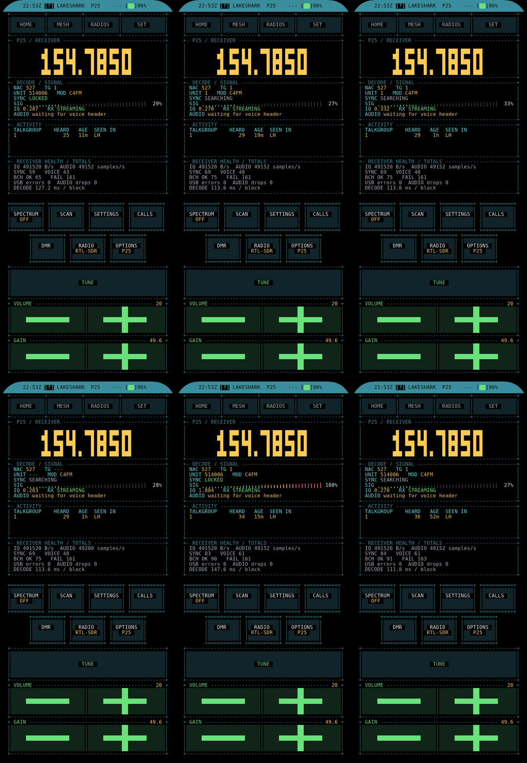
4.1 About this Volume
Volume 3 ended at the USB boundary: an RTL-SDR Blog V3 or V4 dongle, hosted directly by the ESP32-P4’s High-Speed USB OTG port, delivering interleaved 8-bit IQ at up to 2,000,000 samples per second into the firmware with no PC, Pi, or phone in the chain. This volume takes that raw byte stream and follows it all the way to a human voice coming out of the speaker.
That journey — baseband IQ to decimated audio-rate samples to recovered C4FM symbols to Project 25 frames to IMBE-coded speech to PCM on an I2S bus — is the single hardest thing LakeShark does, and it is the reason the project exists at all. A HackRF with a PortaPack can show a waterfall and demodulate analog FM on battery, but following a trunked P25 system and speaking the voice aloud is a software problem, not an RF one, and it is a software problem that normally lives on a desktop running OP25 under Linux. LakeShark moves that software onto a dual-core microcontroller. The interesting engineering is all in how the work is divided and where the corners are cut.
The authoritative source for this pipeline is the project’s own docs/P25_VOICE.md, which names the functions, the sample rates, and the two execution contexts. This volume reproduces that pipeline faithfully, adds the surrounding DSP context an engineer needs to read it, and flags the few places where the documentation itself hedges.
Note — voice and honesty. This is a reference account of a decode chain, not a field report. Where the repository’s own documentation says a stage is bench-tested but not RF-proven, this volume says so in the same breath. Volume 5 collects every one of those caveats into a single honesty ledger; this volume keeps them inline so the pipeline reads straight.
4.2 The whole pipeline on one page
Every later section expands one box of the diagram below. It is worth absorbing as a whole first, because the two-column layout is not decoration — the left column runs on core 1, the right column on core 0, and the arrow crossing the middle is a lock-free sample ring in PSRAM. That hand-off is the architectural spine of the whole design.
 ┌──────────────────────────────────────────────────────────┐
 │ ESP32-P4 dual RISC-V HP │
 │ │
 RTL-SDR │ CORE 1 (p25_rx task) CORE 0 (dsd_decode) │
 ┌──────┐ │ ┌───────────────────────┐ ┌────────────────────┐ │
 │R820T2│ │ │ ls_radio_iq_read │ │ getFrameSync │ │
 │ + │──┼──▶│ 16 KiB IQ block │ │ 24-symbol hunt │ │
 │RTL283│USB│ └──────────┬────────────┘ │ slice @ midpoint │ │
 │ 2U │ HS │ ▼ │ ≤3 errors accepted │ │
 └──────┘480 │ ┌───────────────────────┐ └─────────┬──────────┘ │
 │ │ dsp_process_iq │ ▼ │
 │ │ • LPF + decimate→48kHz │ ┌────────────────────┐ │
 │ │ • DC blocker │ │ processFrame │ │
 │ │ • AGC │ │ NID + BCH(63,16) │ │
 │ │ • FM discriminator │ │ p25_sync_confirm │ │
 │ │ • RRC filter │ └─────────┬──────────┘ │
 │ │ • C4FM DC removal │ ▼ │
 │ └──────────┬────────────┘ ┌────────────────────┐ │
 │ ▼ │ processHDU / LDU1 │ │
 │ ┌───────────────────────┐ │ LDU2: 9×IMBE/LDU │ │
 │ │ DSD_SAMPLE_RING │━━━━━━━▶│ ESS gate │ │
 │ │ (lock-free, PSRAM) │ └─────────┬──────────┘ │
 │ └───────────────────────┘ ▼ │
 │ ┌────────────────────┐ │
 │ │ processMbeFrame │ │
 │ ┌───────────────────────┐ │ IMBE FEC + │ │
 │ │ audio_out task │◀───────│ OP25 vocoder │ │
 │ │ I2S → ES8311 → spkr │ │ (mbelib fallback) │ │
 │ └──────────┬────────────┘ └─────────┬──────────┘ │
 └──────────────┼───────────────────────────────┼────────────┘
 ▼ ▼
 ┌───────┐ audio_write_p25_voice
 │ 🔊 │ 8 kHz → 16 kHz
 └───────┘ 1000 ms ring in PSRAM
Read top-to-bottom, the chain is seven stages:
Table 1 — Read top-to-bottom, the chain is seven stages
| # | Stage | Function (from P25_VOICE.md) | Core | Rate in → out |
|---|---|---|---|---|
| 1 | IQ ingest | ls_radio_iq_read | 1 | up to 2 MSPS → 16 KiB blocks |
| 2 | Front-end DSP | dsp_process_iq | 1 | 240/256 kSPS → 48 kHz |
| 3 | Symbol recovery | C4FM slicer (in DSP) | 1 | 48 kHz → 4800 sym/s |
| 4 | Sync + NID | getFrameSync, processFrame | 0 | 4800 sym/s |
| 5 | Frame parse | processHDU/LDU1/LDU2 | 0 | 9 IMBE frames / LDU |
| 6 | Vocoder | processMbeFrame (OP25) | 0 | 88 bits/20 ms → 8 kHz PCM |
| 7 | Audio out | audio_write_p25_voice, audio_out | 0→1 | 8 kHz → 16 kHz → I2S |
The remainder of this volume walks each row.
4.3 Stage 1 — IQ ingest and the 16 KiB block
The p25_rx task runs on core 1 and does nothing but pull data from the radio and reduce it. Its first act each iteration is ls_radio_iq_read, which returns a 16 KiB block of interleaved unsigned 8-bit IQ — the native RTL2832U output format, two bytes per complex sample, so one block is 8,192 complex samples.
Why 16 KiB and not a full USB transfer buffer? Because the block size is the unit of latency. At the rates P25 uses, a 16 KiB block is a small, fixed slice of time that keeps the FM discriminator’s internal state fresh and bounds how far behind the decoder can fall before the sample ring overflows. It is large enough that the per-call USB and task-switch overhead is amortized, and small enough that the decimation filter downstream never has to chew through a backlog.
The sample rate the dongle is commanded to produce is mode-dependent, not fixed. Different LakeShark modes ask the RTL-SDR for different rates:
Table 2 — The sample rate the dongle is commanded to produce is mode-dependent, not fixed. Different LakeShark modes ask the RTL-SDR for different rates
| Mode | Requested RTL rate | Why |
|---|---|---|
| P25 voice | 240 kSPS | Narrow-band C4FM; whole multiple of the 48 kHz target |
| FM / pagers | 256 kSPS | Slightly wider, aligns with analog FM deviation |
| Wideband scan / waterfall | up to 2 MSPS | Spectrum coverage, not voice |
On a HackRF (experimental transport only — see the caveat below), the device cannot be commanded to 240 kSPS; its sample-rate floor is 2 MSPS. The firmware handles this by running the HackRF at the smallest whole multiple above its 2 MSPS floor and decimating the extra factor in software. The transport has been proven to deliver IQ at 2 MSPS; what has not been observed is a live P25 call decoded off a HackRF front end.
Warning — HackRF is transport-proven, not decode-proven. The USB IQ path from a HackRF One into LakeShark works at 2 MSPS, and pagers decode off it. Live P25 voice over HackRF is listed as unconfirmed by the project. Treat the RTL-SDR Blog V3/V4 as the supported P25 front end; treat HackRF as a lab curiosity until the project says otherwise.
4.4 Stage 2 — dsp_process_iq: filter, decimate, discriminate
dsp_process_iq, in dsp_pipeline.c, is where raw baseband becomes a demodulated audio-rate stream. It is the busiest single function in the radio path and runs entirely on core 1. The documented stage order is:
- Low-pass filter + decimation to 48 kHz. The 240 kSPS (or 256 kSPS) input is band-limited and decimated by 5 (or by a close factor) down to a 48 kHz working rate. The low-pass is the anti-alias guard: it removes everything that would fold into the audio band once the sample count drops.
- DC blocker. A one-pole high-pass that strips the residual DC offset endemic to a zero-IF dongle — the R820T2’s LO leakage shows up as a spike at bin zero, and left in place it biases every downstream estimate.
- AGC. Automatic gain control normalizes the signal envelope so the discriminator and the symbol slicer see a consistent amplitude regardless of how strong the station is.
- FM discriminator. This is the demodulator proper: it recovers the instantaneous frequency of the complex signal, which for a C4FM transmitter is the data. The classic implementation is the argument of the product of each sample with the conjugate of the previous one; the output is a real-valued baseband waveform whose level encodes the four C4FM deviation states.
- RRC filter. A root-raised-cosine matched filter shapes the demodulated stream to the transmit pulse shape, maximizing signal-to-noise at the symbol-decision instant and controlling inter-symbol interference.
- C4FM DC removal. A final DC trim specific to the C4FM constellation, centering the four-level eye so the slicer’s thresholds sit symmetrically.
The output of this stage is a clean, DC-centered, matched-filtered real waveform at 48 kHz, ready to be sliced into symbols. It is handed to the next stage within the same core-1 task.
 IQ (uint8 I/Q) complex float real baseband 4-level eye
 ┌─────────────┐ LPF ┌─────────────┐ FM disc ┌───────────┐ RRC ┌──────────┐
 │ 240 kSPS │─────▶ │ 48 kHz cplx │────────▶ │ 48 kHz re │────▶ │ centered │
 │ from dongle │ decim │ DC-blocked │ + AGC │ freq-demod │ +DCrm│ C4FM wav │
 └─────────────┘ └─────────────┘ └───────────┘ └──────────┘
Two details reward attention. First, the whole chain targets 48 kHz specifically because C4FM runs at 4800 symbols per second: 48,000 / 4,800 = exactly 10 samples per symbol, a clean integer oversample that makes the timing-recovery arithmetic in the next stage simple and exact. Second, every one of these six steps is integer or fixed-point where it can be — the P4’s HP core has an FPU, but the discriminator and filters are the per-sample hot loop, and keeping them cheap is what buys the headroom to run two radios and a GUI at the same time.
4.5 Stage 3 — C4FM symbol recovery and the clock
C4FM (Compatible 4-level Frequency Modulation) is the physical layer of P25 Phase 1. The transmitter shifts the carrier to one of four deviation levels per symbol, 4800 symbols per second, two bits per symbol, for a 9600 bit/s gross rate. Recovering those symbols from the 48 kHz waveform means two things: deciding where each symbol is (timing) and deciding which of four levels it is (slicing).
The slicer takes the sample at the symbol midpoint and maps it to one of four dibit values by comparing against three thresholds. The timing — where that midpoint actually falls — is governed by a symbol clock whose behavior docs/P25_VOICE.md describes precisely:
The C4FM symbol clock moves at every zero crossing while acquiring. Once two frames arrive back to back, it moves only when the accumulated crossing error reaches 4 samples.
This is a gear-shift clock-recovery strategy, and it is a nice piece of pragmatism. During acquisition, the loop is aggressive: it nudges its phase at every zero crossing, chasing lock as fast as the signal allows. Once the decoder has seen two consecutive good frames — i.e., it is confident it is actually tracking a P25 signal — it switches to a sluggish mode, deferring any correction until the accumulated timing error reaches a full 4 samples (out of 10 per symbol). The aggressive mode finds the signal; the sluggish mode stops the loop from jittering itself off a signal it already has. The cost of the simple design is that a brief fade can push the accumulated error past threshold and force a re-acquire.
Note — polarity. C4FM can arrive inverted, and the project documents this as a real operational variable: on the DMR observer path (Volume 5) the stream arrives inverted and needs a specific gain and polarity setting to frame at all. LakeShark exposes polarity as configurable rather than auto-detected on some paths, which is honest about the fact that a four-level eye is symmetric and the firmware cannot always tell “up” from “down” without help.
4.6 Stage 4 — sync, NID and BCH(63,16)
Symbols now cross the DSD_SAMPLE_RING from core 1 to core 0, where the dsd_decode task takes over. Its first job is to find frame boundaries in a continuous symbol stream, and its second is to prove that what it found is really a P25 frame and not noise that happened to look like one.
Sync hunt. getFrameSync slides a 24-symbol window over the stream looking for the P25 frame synchronization pattern. It slices each candidate at the symbol midpoint and accepts a match with up to 3 symbol errors — a correlation threshold loose enough to catch a weak signal, tight enough that random noise rarely trips it across 24 symbols.
NID + BCH. A sync pattern alone is not proof. processFrame reads the Network Identifier (NID) that immediately follows sync and checks it with a BCH(63,16) code. BCH(63,16) is a powerful block code — 63 coded bits carrying 16 information bits — able to correct many bit errors in the NID, which carries the Network Access Code (NAC) and the Data Unit ID (what kind of frame follows). Only after this BCH check passes does the frame count as signal.
Confirmation. The project adds one more gate: a valid frame must also be corroborated by p25_sync_confirm.c. This is a belt-and-suspenders defense against the single most annoying failure mode of a loose sync threshold — a false lock that paints garbage on the screen and squawks noise at the operator. A sync hit that passes the 24-symbol correlation but fails NID BCH, or passes BCH but fails confirmation, is discarded silently.
 symbols ─▶ getFrameSync ─▶ [sync?] ─no─▶ keep hunting
 │yes
 ▼
 read NID (63b)
 │
 BCH(63,16) ─fail─▶ discard, not "signal"
 │pass
 ▼
 p25_sync_confirm ─fail─▶ discard
 │pass
 ▼
 dispatch by Data Unit ID → HDU / LDU1 / LDU2
This three-gate design — correlation, then forward-error-correction, then a second-opinion confirmer — is why the project can quote a specific false-lock statistic in its DMR notes (Volume 5) rather than hand-waving. The level bar on the P25 screen only counts a signal as present after NID BCH passes, which is why a strong carrier of the wrong mode does not light it up.
4.7 Stage 5 — HDU, LDU1, LDU2 and the IMBE frames
Once the Data Unit ID is known, the frame is dispatched to the right parser. A P25 Phase 1 voice call is a repeating superframe of three frame types:
Table 3 — Once the Data Unit ID is known, the frame is dispatched to the right parser. A P25 Phase 1 voice call is a repeating superframe of three frame types
| Frame | Parser | Duration | Carries |
|---|---|---|---|
| HDU (Header Data Unit) | processHDU | 82 ms | Algorithm ID, Key ID, Message Indicator, talkgroup — the call setup, including the ESS |
| LDU1 (Logical link DU 1) | processLDU1 | 180 ms | 9 IMBE voice frames + link control |
| LDU2 (Logical link DU 2) | processLDU2 | 180 ms | 9 IMBE voice frames + encryption sync |
Each LDU carries nine 20 ms IMBE voice frames — 9 × 20 ms = 180 ms, which is exactly the LDU duration. A call is HDU, then LDU1/LDU2 alternating until the user unkeys. The arithmetic is worth internalizing: 50 IMBE frames per second (one every 20 ms), delivered in bursts of nine, is the cadence the whole downstream audio buffer is sized around.
processHDU reads the header including the ESS — the Encryption Sync Status. process_IMBE then applies an ESS gate, which holds or mutes voice. This is the firmware’s handling of encrypted traffic: a P25 call whose ESS indicates an active encryption algorithm cannot be decoded to clear voice (LakeShark is a receiver, not a key-recovery tool), so the gate mutes it rather than emitting a scream of vocoded noise. A p25_voice_hold stage sits alongside, releasing or discarding voice that is being held — the mechanism that lets the decoder buffer a few frames across a brief sync wobble and then either play them out or drop them cleanly.
Note — what “decode” does and does not mean. Parsing the frames of an encrypted call is easy; the NID, the link control, the talkgroup, even the Key ID are all in the clear. What is impossible without the key is turning the IMBE payload into speech. LakeShark will happily show the metadata of an encrypted call and stay silent on the audio. That is the correct and legal behavior, and it is worth stating plainly in a hub whose other tools are far more offensive.
4.8 Stage 6 — the IMBE vocoder: OP25 and mbelib
IMBE (Improved Multi-Band Excitation) is the speech codec of P25 Phase 1. Each 20 ms voice frame is 88 bits after FEC — a spectral model of the speech (fundamental frequency, voiced/unvoiced band decisions, spectral amplitudes) rather than a waveform. Turning those 88 bits back into audio is the job of a vocoder, and this is historically the hardest part to do in open source because the IMBE algorithm was patent-encumbered for years.
processMbeFrame runs the IMBE FEC decode (correcting bit errors in the voice frame using the codec’s own protection) and then the vocoder synthesis. LakeShark uses the OP25 fixed-point imbe_vocoder as its primary engine, with mbelib as a fallback. The distinction is the whole reason the decode runs on a microcontroller at all:
Table 4 — processMbeFrame runs the IMBE FEC decode (correcting bit errors in the voice frame using the codec's own protection) and then the vocoder synthesis. LakeShark uses the OP25 fixed-point imbevocoder as its primary engine, with mbelib as a fallback. The distinction is the whole reason the decode runs on a microcontroller at all
| Vocoder | Arithmetic | Origin | Role in LakeShark |
|---|---|---|---|
OP25 imbe_vocoder | Fixed-point integer | OP25 project (GNU Radio P25 receiver) | Primary — cheap enough for the P4’s HP core |
| mbelib | Floating-point | Open-source MBE family (DSD) | Fallback |
A floating-point MBE synthesizer is comfortable on a desktop CPU and painful on an MCU doing six other things. The OP25 project long ago rewrote the IMBE synthesizer in fixed-point integer math precisely so it could run on constrained hardware, and that fixed-point port is what makes 50 voice frames per second feasible on core 0 of an ESP32-P4 while core 1 is still chewing IQ. The mbelib fallback exists for frames the fixed-point path handles poorly.
The output is 8 kHz PCM — the native IMBE synthesis rate.
4.9 Stage 7 — audio out: resample, I2S, ES8311
The last stage closes the loop to the speaker. audio_write_p25_voice takes the 8 kHz PCM from the vocoder and upsamples it to 16 kHz, writing into a 1000 ms audio ring in PSRAM. A separate audio_out task drains that ring and ships it over I2S to the ES8311 codec, which drives the onboard speaker.
The one-second ring is the elasticity in the system. P25 voice arrives in 180 ms LDU bursts with gaps while the decoder parses link control and hunts the next sync; the audio ring smooths those bursts into continuous sound and absorbs the jitter of a decoder running on a shared core. The 8→16 kHz upsample matches the codec’s preferred rate and gives the speaker path a little more headroom above the 4 kHz top of the IMBE model.
 OP25 vocoder audio_write_p25_voice audio_out task
 ┌──────────┐ 8 kHz ┌───────────────────┐ 16k ┌──────────────┐
 │ 88-bit → │────────▶│ ×2 resample │──────▶│ I2S DMA │
 │ 8 kHz PCM│ │ 1000 ms ring/PSRAM │ │ → ES8311 │──▶ 🔊
 └──────────┘ └───────────────────┘ └──────────────┘
This is also where the spoken callouts in other modes (ADS-B aircraft announcements, Volume 6) and alert tones share the same codec and speaker — the ES8311 is the single audio sink for the whole device, and the I2S path is the common road everything travels to reach it.
4.10 The dual-core split and why it matters
The ESP32-P4’s two high-performance RISC-V cores are not a luxury here; they are load-bearing. The split is clean and deliberate:
Table 5 — The ESP32-P4's two high-performance RISC-V cores are not a luxury here; they are load-bearing. The split is clean and deliberate
| Core | Task | Work | Nature |
|---|---|---|---|
| Core 1 | p25_rx | ls_radio_iq_read → dsp_process_iq → C4FM slicing | Per-sample, soft-real-time, feeds the ring |
| Core 0 | dsd_decode | sync → BCH → frame parse → vocoder | Per-symbol/per-frame, bursty, drains the ring |
The DSD_SAMPLE_RING between them is the decoupler. Core 1 produces symbols at a steady 4800/s; core 0 consumes them in bursts — a quiet stretch during sync hunt, then a flurry during a 180 ms LDU as nine IMBE frames come through the vocoder. A single-core design would have to interleave the steady producer and the bursty consumer by hand, and any time the vocoder ran long the IQ buffer would overflow and the signal would drop. Splitting them lets each run flat-out on its own core and communicate only through a lock-free ring, so a vocoder stall costs at most some audio latency, never a lost signal lock.
Tip — reading the split in the field reports. The project’s own status language maps onto this diagram: “15 of 41 captures decoded” is a core-0 statement (decoder coverage), while “proven at 2 MSPS” is a core-1 statement (ingest and DSP throughput). Keeping the two cores’ claims separate is how the project avoids over-claiming — the transport can be solid while the decoder is still bench-only.
There is one documented wrinkle. On the RTL path, dsd_decode runs on core 0. On the LR2021 path (next section), docs/P25_VOICE.md places dsd_decode on core 1, and the page itself flags the discrepancy: “Check this before relying on either.” The honest reading is that the core assignment shifts with the front end, and the documentation has not fully settled which is canonical.---
4.11 The LR2021 no-SDR path
The LR2021 board variant (introduced in Volume 2) is the one that needs no RTL-SDR at all: the transceiver itself streams raw IQ over SPI, and that stream feeds the same DSP and decoder described above. This is the cleverest integration in the whole project, and it is worth tracing because it reuses the C4FM pipeline almost unchanged.
 LR2021 ──SPI──▶ capture task (core 0) p25_rx frontend (core 1)
 ┌──────┐ IQ16 ┌──────────────────────┐ ┌──────────────────────────┐
 │raw IQ│───────▶│ 125k complex/s │────▶│ resample 125 → 240 kHz │
 │ RX │ 125k │ 8-block checked queue │ │ float IQ │
 └──────┘ └──────────────────────┘ │ → C4FM DSP → 48 kHz │
 │ → sample ring → dsd_decode│
 └──────────────────────────┘
The differences from the RTL path:
- Ingest rate is 125,000 complex pairs/s over SPI, not up to 2 MSPS over USB. That is a fraction of the RTL ceiling — enough for a single narrow-band P25 or FM channel, but with no band-scan and no Phase II on this path.
- A capture task on core 0 reads IQ16 into an eight-block checked queue (the “checked” part matters:
p25 lr modereports accepted blocks, rejected sessions, gaps, and FIFO loss, so overruns are counted rather than silently dropped). - The
p25_rxfrontend on core 1 resamples 125 kHz → 240 kHz float IQ and then runs the identical C4FM DSP down to 48 kHz. From the sample ring onward it is the same decoder. - C4FM is fixed while LR IQ is active — the demod cannot be switched — though polarity remains configurable. The antenna must be selected under RADIOS > ANTENNA (MMCX1 is the external connector). Holds use
ls_mesh_radio_hold_bgrather than the RTL path’s hold.
The design lesson is that LakeShark’s DSP is written against an abstract IQ source, not against the RTL dongle specifically. Resample an SPI stream up to 240 kHz and the entire C4FM-to-IMBE chain works unmodified. That abstraction is what let a single transceiver chip replace a whole USB dongle for the narrow-band voice use case — at the price of the scanning bandwidth a real SDR gives.
Note — the two-variant reality. A buyer chooses at purchase between an SX1262 board (needs an RTL-SDR for P25/FM/ADS-B) and an LR2021 board (onboard SDR RX, no scanning, no Phase II). The firmware auto-detects which is present at boot. Volume 2 covers the hardware fork; this volume is why the fork exists — the LR2021 trades the RTL’s bandwidth and Phase II for a dongle-free single-channel receiver.
4.12 Open-source lineage: OP25, mbelib, DSD
None of the decode intelligence above is original to LakeShark, and the project is explicit about that. What LakeShark did was port and integrate a well-known open-source P25 stack onto a microcontroller. The lineage:
Table 6 — None of the decode intelligence above is original to LakeShark, and the project is explicit about that. What LakeShark did was port and integrate a well-known open-source P25 stack onto a microcontroller. The lineage
| Component | Upstream project | What LakeShark took |
|---|---|---|
| IMBE vocoder (fixed-point) | OP25 (GNU Radio P25 receiver) | The imbe_vocoder fixed-point synthesizer — the core-0 workhorse |
| MBE synthesis (fallback) | mbelib / DSD family | Floating-point fallback vocoder |
| Frame sync, NID/BCH, frame parsing | DSD (Digital Speech Decoder) heritage | getFrameSync, the frame-state machine conventions |
| librtlsdr USB host (Volume 3) | XTR1984/xtrsdr (ESP-optimized librtlsdr) | The USB-host RTL driver on ESP-IDF |
The significance for an engineer evaluating the tool is that the algorithms are the same ones a desktop OP25 user relies on — the same vocoder math, the same FEC, the same sync strategy. The risk surface is therefore not “did someone reimplement IMBE badly on an MCU” but “did the port preserve the upstream’s numeric behavior under fixed-point and the P4’s memory model.” That is a much smaller and more testable question, and it is why the honesty ledger (Volume 5) can be specific: the decoder is trusted where the upstream is trusted, and flagged where the MCU port has not yet been exercised against live RF.
GPL-3.0 governs LakeShark itself; the imported components keep their own licenses (OP25 and the MBE family are GPL-family too), recorded in docs/THIRD_PARTY_NOTICES.md. Volume 10 draws the full credit map.
4.13 Takeaways
- The decode chain is seven stages across two RISC-V cores: ingest and DSP on core 1, sync-through-vocoder on core 0, joined by a lock-free
DSD_SAMPLE_RINGin PSRAM. The split is what makes real-time P25 on an MCU possible. - The 48 kHz working rate is chosen for arithmetic: 10 samples per C4FM symbol at 4800 sym/s. The gear-shift symbol clock chases lock aggressively, then goes sluggish once two frames arrive back-to-back.
- Three gates guard against false lock: 24-symbol correlation (≤3 errors), NID BCH(63,16), and
p25_sync_confirm. A signal only “counts” after BCH passes. - A P25 call is HDU (82 ms) then LDU1/LDU2 (180 ms, 9 IMBE frames each); the ESS gate mutes encrypted voice rather than synthesizing noise.
- The vocoder is OP25’s fixed-point
imbe_vocoder(primary) with mbelib fallback — the fixed-point port is the enabling trick for MCU-class hardware. Output is 8 kHz PCM, upsampled to 16 kHz into a 1 s PSRAM ring, out over I2S to the ES8311. - The LR2021 no-SDR path resamples a 125 kcomplex/s SPI stream up to 240 kHz and reuses the identical C4FM-to-IMBE chain — at the cost of band-scan and Phase II.
- The whole decoder is ported, not invented: OP25, mbelib, and DSD heritage, the same algorithms a desktop OP25 user trusts. That is the basis for the honesty ledger in Volume 5.
Volume 5 takes the frame parser and asks the uncomfortable questions: what has actually been received off the air, what is only bench-tested, and how the DMR observer trick reads a second protocol out of the same symbol stream.
Comments (0)