LakeShark · Volume 5
LakeShark Volume 5 — Digital-Voice & Paging Decode
P25 trunking, the DMR observer trick, POCSAG, SAME/EAS — and an honest ledger of what has met real RF
5.1 About this Volume
Volume 4 built the machine: IQ in, C4FM symbols recovered, P25 frames parsed, IMBE synthesized to speech. This volume is about what that machine is pointed at — the modes and protocols LakeShark decodes beyond a single conventional P25 call, and, just as importantly, how confident the project is in each of them.
That second half is unusual enough to be the organizing principle of this volume. Most firmware marketing claims a feature works the moment the code compiles. LakeShark’s documentation does the opposite: it distinguishes, mode by mode, between what has actually been received off the air, what has only been tested against recorded captures on the bench, and what has merely been proven at the symbol level without ever seeing a real transmitter. The project states its own decode ceilings in plain numbers — “15 of 41 captures,” “7% of bits wrong even on a noiseless signal,” “never received a real DMR transmitter.” Reproducing that honesty faithfully is the point of §10, and it is a genuine strength of the tool, not a weakness to paper over.
Note — why the honesty matters to a buyer. A scanner that over-claims is worse than useless in the field: the operator trusts a decode that is actually noise. A tool that tells you “this mode is bench-only” lets you plan around it. The ledger in §10 is the single most decision-relevant page in this whole dive for anyone choosing between LakeShark and a commercial scanner.
5.2 P25 Phase 1: conventional vs trunked
Project 25 (P25) is the digital land-mobile-radio standard used by most US public-safety agencies. Phase 1 is the C4FM physical layer decoded in Volume 4. There are two ways agencies deploy it, and LakeShark handles both:
Table 1 — Project 25 (P25) is the digital land-mobile-radio standard used by most US public-safety agencies. Phase 1 is the C4FM physical layer decoded in Volume 4. There are two ways agencies deploy it, and LakeShark handles both
| Deployment | What it is | LakeShark support |
|---|---|---|
| Conventional | Fixed channel; transmitter and receiver on the same frequency, like an analog repeater but digital | Full, on the supported front ends |
| Trunked | A computer-controlled pool of channels; a control channel assigns a voice frequency per call | Full on RTL-SDR; the hard case |
The P25 app, per the project’s own description, supports “Phase I trunking and conventional digital voice,” with automatic or manual demodulation, channel lists, a DMR activity view, and a call archive.
The AUTO/manual choice is more consequential than it sounds. The Volume 4 pipeline has a gain-and-polarity surface that is not fully self-tuning (C4FM can arrive inverted; the DMR path needs an explicit -9000 gain). AUTO lets the firmware chase lock on its own; manual pins the demodulator so a marginal signal is not abandoned every time the auto logic re-hunts. The two interact with the clipping philosophy of §10 — an over-gained front end that AUTO keeps re-acquiring is often better served by pinning the demod manually and backing the gain off.
Table 2 — P25 Phase 1: conventional vs trunked
| Control | Effect | When to reach for it |
|---|---|---|
| AUTO demod | Firmware selects/retries the demod | Clean, strong signal; unattended scan |
| Manual demod | Pins the chosen demod | Marginal signal AUTO keeps dropping |
| Channel lists | Named frequencies, including mixed P25/FM in one list | Monitoring a mix of digital and analog |
| DMR activity view | Reports digital activity the receiver sees (§5) | Recognizing DMR on a watched frequency |
| Call archive | Records calls to SD for later review | Logging, evidence, offline review |
The mixed P25/FM channel list is worth calling out: a single scan list can contain both digital P25 and analog FM entries, and the firmware switches decode mode per channel. That is the behavior that lets one list cover a realistic local radio landscape where dispatch is P25 but a mutual-aid or business channel is still analog.
Conventional is the easy case: tune the channel, run the Volume 4 pipeline, decode voice. Trunking is where a scanner earns its keep, and it is also where the two board variants diverge sharply:
- SX1262 variant: Phase I trunking requires an RTL-SDR Blog V3/V4. Trunk-following needs the bandwidth and agility an RTL dongle provides; the onboard SX1262 is a LoRa/MeshCore radio, not an SDR.
- LR2021 variant: lists onboard P25 voice — but on the LR2021’s 125 kcomplex/s SPI path there is no band-scan (Volume 4), which constrains how it can follow a trunked system versus the RTL path’s full-bandwidth view.
5.3 Following a trunked system on one receiver
Trunk-following is the defining trick of a digital scanner, and it is worth spelling out because it is what separates LakeShark from a dumb single-frequency demodulator.
In a trunked system there is no fixed “fire department channel.” Instead a control channel continuously broadcasts, in the clear, a stream of data that says things like “talkgroup 1203 is now on voice channel 7.” A scanner that wants to follow a given talkgroup must:
- Decode the control channel continuously.
- Watch for a channel-grant message naming a talkgroup of interest.
- Retune the receiver to the assigned voice frequency fast enough to catch the call.
- Decode the voice (the Volume 4 chain).
- Return to the control channel when the call ends.
 ┌──────────────── CONTROL CHANNEL (always decoded) ────────────────┐
 │...grant TG1203 → VC7......grant TG0450 → VC3......idle... │
 └───────────────────────────┬──────────────────────────────────────┘
 │ grant for a watched talkgroup
 ▼
 retune to voice channel
 │
 ┌─────────▼──────────┐
 │ Volume 4 pipeline │ ◀── decode the call
 │ C4FM → IMBE → 🔊 │
 └─────────┬──────────┘
 │ call ends
 ▼
 return to control channel
The reason this needs an RTL-SDR on the SX1262 board is latency and bandwidth: steps 1 and 3 fight each other. A receiver that can see a wide enough slice of spectrum can watch the control channel and jump to a voice channel within the same tuner without a slow physical retune. The RTL’s up-to-2-MSPS front end (Volume 3) gives that headroom; the LR2021’s 125 kcomplex/s SPI window does not, which is exactly why the project does not claim full trunk-scan on the LR2021 path.
The DMR activity view sits alongside the P25 decode here — a panel that reports digital activity the receiver sees even when it is not a P25 voice call, which is where the observer trick of §5 lives. The call archive records calls to the SD card for later review.
Warning — the legal envelope. Receiving unencrypted public-safety voice is legal in many jurisdictions and prohibited in others, and acting on intercepted communications is regulated separately again. Trunk-following makes it trivial to follow specific talkgroups, which raises the stakes. The hub’s standing rule applies: own the hardware or have written authorization, and know your local law before you listen. See
../_shared/legal_ethics.md.
5.4 P25 Phase II — experimental
P25 Phase II replaces Phase 1’s C4FM with H-DQPSK TDMA — two voice timeslots per 12.5 kHz channel, a different physical layer and a different vocoder arrangement (AMBE+2). It roughly doubles channel capacity and is increasingly common on large trunked systems.
LakeShark labels Phase II [EXPERIMENTAL], and the project is specific about what that means:
- It is bench-tested with public recordings.
- Live RF is unverified — it has not been confirmed decoding a real Phase II transmission off the air.
- It is disabled after restart — the operator must explicitly re-enable it each boot, which is a deliberate “do not trust this yet” guardrail.
- It is not available on the LR2021 no-SDR path (Volume 4: the 125 kcomplex/s SPI window does not support it).
The honest reading: Phase II is a work in progress that the project ships behind a per-boot opt-in rather than hiding or over-claiming. For an agency on Phase II trunking, LakeShark today is not a substitute for a commercial scanner that handles Phase II as a shipping feature. For a Phase 1 system it is a genuine on-device decoder.
5.5 The DMR observer trick
This is the cleverest decode idea in the whole project, and it falls straight out of a coincidence in the physical layers. DMR is 4FSK at 4800 symbols per second — exactly the same symbol rate as P25 C4FM. Because the rates match, DMR bursts pass straight through LakeShark’s P25 sync hunt without any DMR-specific front end.
The project exploits this with dmr_watch: a read-only observer attached via a function pointer to getFrameSync(). As the P25 decoder hunts sync over the symbol stream, the observer taps that same stream, frames it as DMR (trying both polarities), and reports what it finds — all without disturbing the P25 path. The dmr report includes Slot Type and BPTC outcomes, the last burst’s class and color code, and the last Link Control.
 symbol stream (4800 sym/s)
 │
 ┌────────┴─────────┐
 ▼ ▼
 getFrameSync dmr_watch (observer, read-only)
 (P25 path) ├─ frame both polarities
 │ ├─ Slot Type, BPTC
 ▼ ├─ color code, burst class
 P25 voice └─ Link Control ◀── only this counts as "DMR"
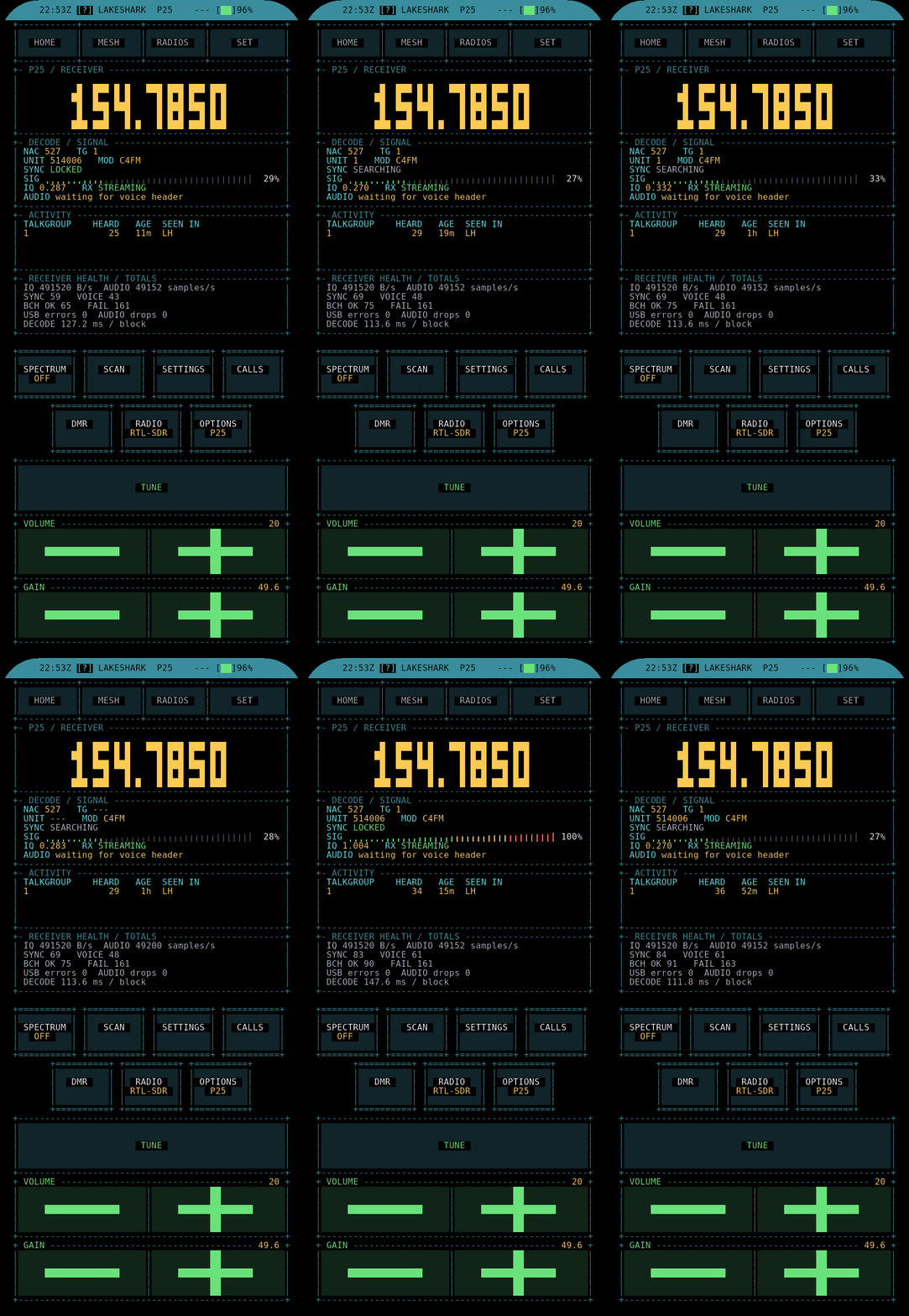
The discipline in the design is what makes it trustworthy: only a valid Link Control counts as evidence of DMR. The documentation gives a worked example on 154.7850 MHz (a P25 frequency): “no DMR — 35 sync hit(s), 1 through BPTC, none carried a valid link control.” Thirty-five raw sync hits sound like a signal; zero valid Link Controls say it is not DMR. The observer refuses to call it DMR until the RS-protected Link Control decodes cleanly.
A dmr report reads roughly like the worked example the documentation gives — a running tally of what the observer has seen on the current frequency, with a verdict that leans entirely on Link Control:
> dmr
freq 154.7850 mode P25(C4FM)
sync hits........ 35
through BPTC..... 1
valid link ctrl.. 0
colour code...... --
last burst class. (none framed)
verdict: no DMR — 35 sync hit(s), 1 through BPTC,
 none carried a valid link control
Thirty-five sync hits is the kind of number a naive detector would report as “DMR present.” The observer refuses the call because nothing survived BPTC and produced a valid Link Control. That refusal is the design — it is the same distrust-the-easy-indicator instinct as the clipping meter in §10.
And the project is brutally honest about the limits:
- The board has never received a real DMR transmitter. The entire DMR capability is symbol-level and bench-only.
- IQ framing is not proven.
test_dmr_over_iqonly checks that a burst is recoverable at the right polarity — and the documentation notes that about 7% of bits are wrong even on a noiseless signal.test_dmr_watchcovers framing from symbols only. - C4FM in this context needs a gain of -9000; at unity gain the pipeline returns silence and C4FM arrives inverted — a reminder that polarity and gain are hand-set variables here, not auto-negotiated.
Note — what the DMR trick is for. It is a detector and identifier, not a DMR voice decoder. It tells the operator “there is DMR activity on this frequency, here is its color code and Link Control” — useful for spectrum reconnaissance and for recognizing that a signal the P25 decoder keeps half-syncing on is actually DMR. It does not produce DMR audio, and the project does not claim it does.
5.6 The analog FM app: scan, CTCSS/DCS, mixed lists
Before the paging and packet modes, it is worth describing the host they all share. The FM app is LakeShark’s analog receiver, and it is the parent menu under which POCSAG, SAME/EAS, APRS, and AIS all live. The project’s description: “Analog FM/AM, band scanning,” CTCSS/DCS, and mixed P25/FM channel lists, plus an experimental Location scanning mode (GPS filtering and CSV/JSON import).
The analog side is the forgiving, well-proven foundation of the whole receiver — the modes with the widest signals and the lowest decode bar. It is also where two features that matter for monitoring real systems live:
Band scanning sweeps a range and stops on activity. On the RTL path the up-to-2-MSPS front end (Volume 3) gives a wide scan; the FM/pager modes request 256 kSPS from the dongle (Volume 4’s rate table) for the per-channel demod once the scan stops.
CTCSS and DCS are the sub-audible squelch systems analog users rely on. CTCSS (Continuous Tone-Coded Squelch System) adds a low-frequency tone (67–254 Hz) beneath the voice; DCS (Digital-Coded Squelch) adds a low-rate digital code. Repeaters and radio users key specific tones so a receiver only opens squelch on their traffic. LakeShark decoding CTCSS/DCS means the operator can identify which tone a conversation is using — useful for separating co-channel users and for programming a radio to match.
Table 3 — The analog FM app: scan, CTCSS/DCS, mixed lists
| Analog feature | What it does | Decode confidence |
|---|---|---|
| FM / AM demod | Voice and AM aircraft-band listening | High — wide signal |
| Band scanning | Sweep + stop-on-activity | High |
| CTCSS / DCS | Identify sub-audible squelch tone/code | Analog, well-understood |
| Mixed P25/FM lists | One scan list, both modes | Per-channel mode switch |
| Location scanning | GPS-filtered channels, CSV/JSON import | Experimental |
Note — Location scanning is experimental. The GPS-filtered channel feature (load a CSV/JSON of frequencies, scan only those relevant to the current position) is labeled experimental by the project. It is the natural fusion of the GPS (Volume 6) and the scanner, but it is not a settled feature.
The analog FM app is, in practice, where a new operator should start: it exercises the IQ-to-audio chain with the least that can go wrong, and every digital mode in this volume is a harder variation on the same front end.
5.7 POCSAG paging
POCSAG is the old, robust, still-ubiquitous pager protocol — FSK, fixed codewords, used by hospitals, fire dispatch, and industrial telemetry. It is one of the most satisfying things to decode because the messages are usually in the clear and arrive as plain text.
In LakeShark, POCSAG lives under the FM app. Its status is better than most of the digital modes:
- Pagers are verified on the HackRF path. This is notable — HackRF is “experimental transport” for P25 (Volume 4), but for pagers the project explicitly says the HackRF path is verified. Pagers are a lower bar than trunked voice: a wider, more forgiving signal that survives the HackRF’s 2 MSPS floor and software decimation.
- POCSAG is supported on the SX1262 variant — i.e., it is one of the modes that works on the LoRa-radio board, not only on the SDR path.
The decode runs at the FM app’s working rate (the project’s FM/pager modes request 256 kSPS from the RTL-SDR; see Volume 4’s rate table). Decoded pages are text and are archived like other received traffic.
Mechanically, POCSAG is a simpler decode than any of the voice modes, which is why it is better-proven. The protocol is 2-FSK at 512, 1200, or 2400 baud, organized into batches of 32-bit codewords (an address codeword or a message codeword), each protected by a BCH(31,21) code plus a parity bit. After the FM discriminator (the same Volume 4 stage), the decoder slices the FSK into bits, finds the frame synchronization codeword, and walks the batch structure:
 preamble ─▶ frame-sync codeword ─▶ batch of 8 frames (2 codewords each)
 ┌──────────────────────────────┐
 │ addr codeword → RIC (pager ID)│
 │ msg codeword → text/numeric │
 │ BCH(31,21) corrects bit errors│
 └──────────────────────────────┘
Because the signal is wide, the FEC is strong, and the content is usually plain text, POCSAG is the mode most likely to produce a clean, repeatable decode on a bench — which is exactly why the project was able to verify it on both the HackRF and SX1262 paths.
Tip — pagers as the “does the whole chain work” smoke test. Because POCSAG is verified on both the HackRF and SX1262 paths, it is the mode most likely to produce a clean, repeatable result on a bench without a live P25 system to listen to. It exercises IQ ingest, DSP, FSK demod, and the archive without needing a trunked system or a key.
5.8 SAME / EAS alerts
SAME (Specific Area Message Encoding) is the digital header burst on NOAA Weather Radio and the Emergency Alert System — the data that precedes the attention tone and encodes event type, affected counties (FIPS), and duration. LakeShark lists “SAME/EAS alerts” under the FM app.
The project gives no further detail than that it is listed, so this volume states only what is documented: SAME/EAS decoding is present under the FM app alongside POCSAG, APRS, and AIS, driven by the same analog FM front end. A fuller characterization — which SAME fields are parsed, whether county filtering is supported — would require bench observation that has not been done here.
For context on what a full SAME decoder could surface: the SAME header is a 520.83 baud AFSK burst, sent three times for redundancy, encoding an originator, an event code (e.g. TOR tornado warning, SVR severe thunderstorm), a list of affected FIPS county/area codes, a purge time, and a timestamp. A weather-radio listener’s most-wanted feature is county filtering — alert only on events for the operator’s own FIPS codes — which pairs naturally with LakeShark’s GPS (Volume 6). Whether the firmware parses to that depth is exactly the kind of claim this dive will not make without seeing it, hence the verify marker above.---
5.9 APRS and AIS
Two more packet modes ride the FM front end:
Table 4 — Two more packet modes ride the FM front end
| Mode | What it is | Where it surfaces |
|---|---|---|
| APRS | Amateur Packet Reporting System — AX.25/Bell-202 AFSK at 1200 baud on VHF; position beacons, telemetry, messages | FM app; positions also plotted in MAP |
| AIS | Automatic Identification System — GMSK maritime vessel beacons at ~162 MHz | FM app; ships plotted in MAP |
Both are listed under the FM app, and both feed the mapping stack: APRS stations and AIS ships appear as live objects on the offline MAP (Volume 6), alongside aircraft trails and mesh nodes. The README does not state the exact frequencies the firmware uses for either (APRS is regionally 144.39 MHz in North America, 144.80 MHz in much of Europe; AIS is 161.975/162.025 MHz), so those are not claimed here as firmware behavior.
The integration story is the interesting part: APRS and AIS are not isolated decoders but data sources for the map. A position-reporting mode is far more useful plotted than printed, and LakeShark’s decision to pipe both into the same offline PMTiles map as ADS-B traffic is what turns a scanner into a situational-awareness tool. Volume 6 covers that map in full.
5.10 The P25 signal panel and clipping indicator
A recurring theme in the project’s documentation is distrust of the naive signal-strength bar, and the P25 signal panel is the worked example. The problem: a simple level bar cannot tell a strong signal from a saturated front end. A dongle driven into clipping shows a pegged meter that looks like a great signal and decodes like garbage.
LakeShark’s answer is to measure the share of IQ components pinned at 0 or 255 — the rails of the 8-bit ADC — rather than the envelope level. When that clipped fraction crosses one fifth (the P25_CLIP_SHOW_PCT threshold in scr_p25.c), a clipping indicator appears. The documented bench measurement: on 154.7850 MHz at 49.6 dB gain, 5,792 of 16,384 IQ components clipped during a call — well over a third, a clear over-gain condition. The project gives 26 dB as the working gain for that session and notes, with characteristic candor, that the 26 dB figure “comes from the bench session and is not recorded elsewhere.”
 gain too high gain right (~26 dB)
 ┌───────────────┐ ┌───────────────┐
 │▓▓▓▓▓▓▓▓▓▓▓▓▓▓▓│ 5792/16384 clipped │ ▂▃▅▆▅▃▂ ▁▂▃▁ │ few rails
 │ CLIP ⚠ │ (>1/5 → indicator) │ clean eye │
 └───────────────┘ └───────────────┘
Note — a bench-covered, not glass-proven feature. The clipping indicator is tested on the bench but, per the project, has not yet been seen on the display during a live call. It is in §10’s ledger as bench-covered. The design is sound; the field confirmation is pending.
This is the signal-quality philosophy worth taking away: measure the thing that actually predicts decode failure (ADC clipping), not the thing that is easy to show (envelope level). It is the same instinct that produced the three-gate false-lock defense in Volume 4.
5.11 The honesty ledger — RF-proven vs bench-only
This is the decision-relevant heart of the volume. The project does not present a flat feature list; it grades each capability by how thoroughly it has been verified. Collected here, with the project’s own language preserved:
Table 5 — This is the decision-relevant heart of the volume. The project does not present a flat feature list; it grades each capability by how thoroughly it has been verified. Collected here, with the project's own language preserved
| Capability | Status | What “status” means here |
|---|---|---|
| P25 Phase 1 conventional | RF-capable on supported front ends | The core Volume-4 chain; the primary claim |
| P25 Phase 1 trunking | Supported (RTL-SDR on SX1262; onboard on LR2021) | Needs RTL-SDR on the SX1262 board |
| P25 Phase II | Experimental | Bench-tested on public recordings; live RF unverified; disabled after restart |
DMR (dmr, dmr_watch) | Symbol-level only | Board has never received a real DMR transmitter; RF path not proven |
| DMR over IQ | Asserts polarity recovery, not framing | test_dmr_over_iq checks recoverability; ~7% bit errors even noiseless |
| POCSAG paging | Verified on HackRF path; on SX1262 | One of the better-proven modes |
subghz_pwm / subghz_nrz | Offline-capture tested | 15 of 41 Flipper RAW captures decode; the project calls this the honest ceiling (Volume 8) |
| P25 clipping indicator | Bench-covered | Tested on the bench; not yet seen on the display during a live call |
| ADS-B 1090 MHz | Capable (Volume 6) | dump1090/libmodes lineage |
| HackRF transport (P25) | Experimental | IQ at 2 MSPS proven; live P25 decode unobserved |
| LoRa compass bearing | Not a validated DF system (Volume 7) | Fox-hunting aid only |
| CELL WATCH | RF baseline survey (Volume 8) | Explicitly NOT an IMSI-catcher detector |
Reading the ledger, a pattern emerges. The modes that touch a wide, forgiving analog signal (FM, POCSAG, ADS-B) are the best proven. The modes that need a specific live digital transmitter to validate (DMR RF, Phase II, the clipping indicator on glass) are honestly marked as unproven against real RF even when the symbol-level or bench logic is complete. And the decoders that run against recorded files (sub-GHz) have an exact, published hit rate rather than a vague “supported.”
Warning — do not round these up. The temptation with any capable tool is to read “bench-tested” as “works.” The project’s own framing resists that, and this dive follows it. A statement like “a wrong device name is worse than a payload the operator reads themselves” (the sub-GHz caveat, Volume 8) is the design ethic. Where the ledger says experimental or symbol-only, treat the feature as a research subject, not a field capability.
The ledger is also a roadmap. Near-daily releases (Volume 1 noted v2.15.0 on 2026-10-15) mean rows migrate from bench-only toward RF-proven over time. Any serious evaluation should re-read the current docs/P25_VOICE.md and docs/TDP4_DECODERS.md for the state on the day, because the honest answer to “does DMR RF work yet” is version-dated.
5.12 Takeaways
- LakeShark decodes P25 Phase 1 conventional and trunked on-device. Trunk-following needs an RTL-SDR on the SX1262 board; the LR2021 does onboard voice but without band-scan.
- P25 Phase II is experimental: bench-tested on recordings, live RF unverified, disabled every restart, unavailable on the LR2021 path.
- The DMR observer trick exploits the shared 4800 sym/s rate —
dmr_watchtapsgetFrameSync()read-only and only calls it DMR on a valid Link Control. It is a detector/identifier, symbol-level only; no real DMR transmitter has ever been received (~7% bit errors even noiseless). - POCSAG is among the best-proven modes — verified on the HackRF path and supported on SX1262 — and makes the best bench smoke-test. SAME/EAS, APRS, and AIS ride the same FM front end; APRS/AIS feed the MAP.
- The P25 signal panel measures ADC clipping share, not envelope level (indicator at >1/5 clipped,
P25_CLIP_SHOW_PCT); bench-covered but not yet confirmed on a live call. - The honesty ledger is the project’s signature strength: well-proven for wide analog modes, explicitly unproven-against-RF for DMR, Phase II, and the clipping indicator. Re-read the live docs before trusting any bench-only row — releases are near-daily.
Volume 6 leaves voice behind for the other half of the receiver: 1090 MHz ADS-B with spoken aircraft callouts, the FALLS waterfall, and the offline PMTiles mapping stack that ties aircraft, ships, APRS, and mesh nodes onto one map with no network.
Comments (0)