SquachWatch · Volume 4
SquachWatch Volume 4 — Building it
The bare board is the whole device: the case, the power path, the SD card, the optional GPS and the first power-on
4.1 What building a SquachWatch means
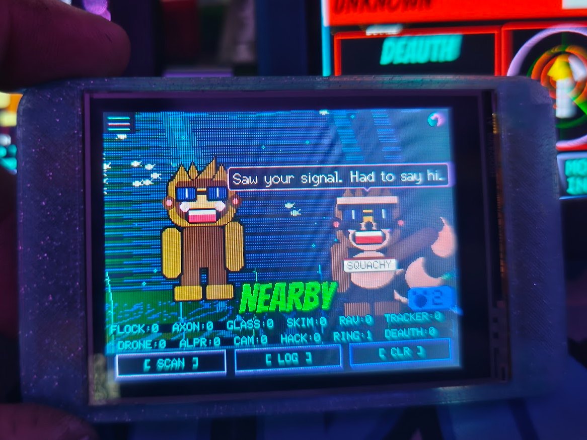
There is very little to build. The project’s own build guide states the requirement for the reference board as an ESP32-2432S028R, a USB-C data cable and a computer, and then: “That’s it. No soldering, no extra components.” The README makes the same point about the 2.8” CYD — “No GPS, no extra modules; the board is the whole device.” Everything in this volume is therefore optional finishing: a printed enclosure, a battery or power bank, a microSD card for the CSV log, and — for one unreleased build variant — a GPS module on two wires.
The sequence, end to end, is the one below. Vol 5 covers the flashing step itself; this volume covers everything physical on either side of it.
  ┌──────────────┐   ┌──────────────┐   ┌──────────────┐   ┌──────────────┐
  │ 1. Inspect   │──▶│ 2. Flash     │──▶│ 3. First     │──▶│ 4. Case it,  │
  │    the board │   │    (Vol 5)   │   │    power-on  │   │    power it, │
  │    bare      │   │    bare      │   │    checks §7 │   │    card it   │
  └──────────────┘   └──────────────┘   └──────────────┘   └──────────────┘
          │                                                         │
          └───── optional: wire the ATGM336H GPS (§6) before ───────┘
                 closing the case, only on a cyd-gps build
Flashing and checking the board before it goes into a case is the practical order: the BOOT button may be needed to force download mode (Vol 5 §5), a wrong display build shows up as a white screen that is easier to diagnose with the board in hand, and touch calibration runs on the very first boot.
4.1.1 Build tiers
Table 1 — 1.1 Build tiers
| Tier | What it adds | Source of the parts list | Firmware build |
|---|---|---|---|
| Bare board | Nothing — CYD + USB cable | docs/BUILD.md | cyd-fast / cyd / cyd-ili9341 |
| Cased | 3D-printed enclosure | Talking Sasquach’s launch video points at MakerWorld model 3383046 | unchanged |
| Portable | USB power bank, or a LiPo with an external charger/boost stage | docs/FAQ.md “Battery and power” | unchanged; CHARGE MODE and LAST RUN apply |
| Logging | FAT32 microSD in the onboard slot | docs/BUILD.md, include/sd_log.h | unchanged |
| GPS / wardriving | ATGM336H module on GPIO 35 | docs/PINOUT.md | cyd-gps / cyd-ili9341-gps — built from source only |
| Pre-built | RL Phantom 2.4” from Rabbit Labs | launch video description | rlphantom-r |
Parts, prices and sellers for each tier are Vol 3’s subject; the board itself is Vol 2’s.
4.2 Bench kit and pre-flight
4.2.1 What to have on the bench
Table 2 — 2.1 What to have on the bench
| Item | Why | Notes |
|---|---|---|
| USB-C cable that carries data | Flashing and the serial console | ”charge-only cables are the most common cause” of a failed connection |
| Desktop browser with Web Serial, or PlatformIO | Flashing (Vol 5) | Phones and tablets cannot flash |
| Serial terminal able to run at 2,000,000 baud | Boot log, GPS/TIME/ZONE console commands | ”At 115200 it reads as garbage.” |
| microSD card, FAT32 | Optional CSV log | §5 |
| Molex PicoBlade (often sold as “1.25 mm JST”) 4-pin leads | Optional GPS on P3/CN1; optional VIN feed on P1 | Connector naming per the witnessmenow CYD reference |
| ATGM336H GPS module | Only for the cyd-gps builds | §6 |
| A known Bluetooth or Wi-Fi target | First-detection test | §7.3 |
4.2.2 Inspect the bare board
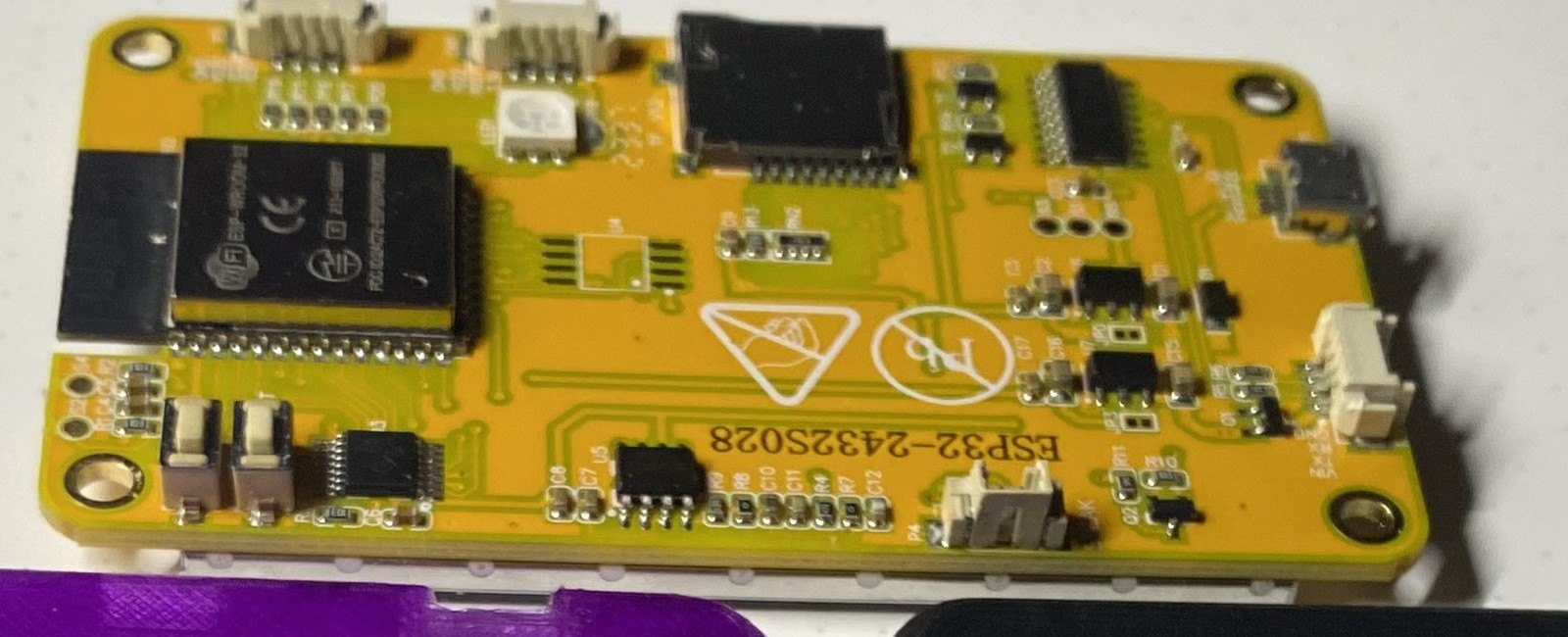
Two things on the board decide which firmware build it needs, and both are worth recording before anything is flashed:
- The code on the back. The web flasher’s board finder reads it, and the last letter is the touch type: “R resistive (press), C capacitive (tap).” An ESP32-2432S028R is the reference board.
- The display controller is invisible. The 2.8” board “ships with EITHER an ST7789 or an ILI9341 panel depending on manufacturing batch, same glass/pinout either way, and there’s no way to tell which from the outside.” The only test is to flash and look (Vol 5 §5.2).
Note — Keep a note of the board’s MAC address once it is known (the web flasher’s IDENTIFY MY BOARD button prints it, Vol 5 §3.1). The project’s own maintainer tooling keys every bench board by MAC precisely because two boards of different display batches are otherwise indistinguishable.
4.3 The case
The project repository does not ship or specify an enclosure — there is no case file, and no case is mentioned in README.md, docs/BUILD.md or docs/FAQ.md. The case recommendation comes from Talking Sasquach’s launch video, whose description points at a MakerWorld model titled “The Best 2.8” CYD Case — no extra hardware” (model 3383046, https://makerworld.com/en/models/3383046). Its print settings, fit and retention method were not verified for this volume; follow the model page’s own notes.
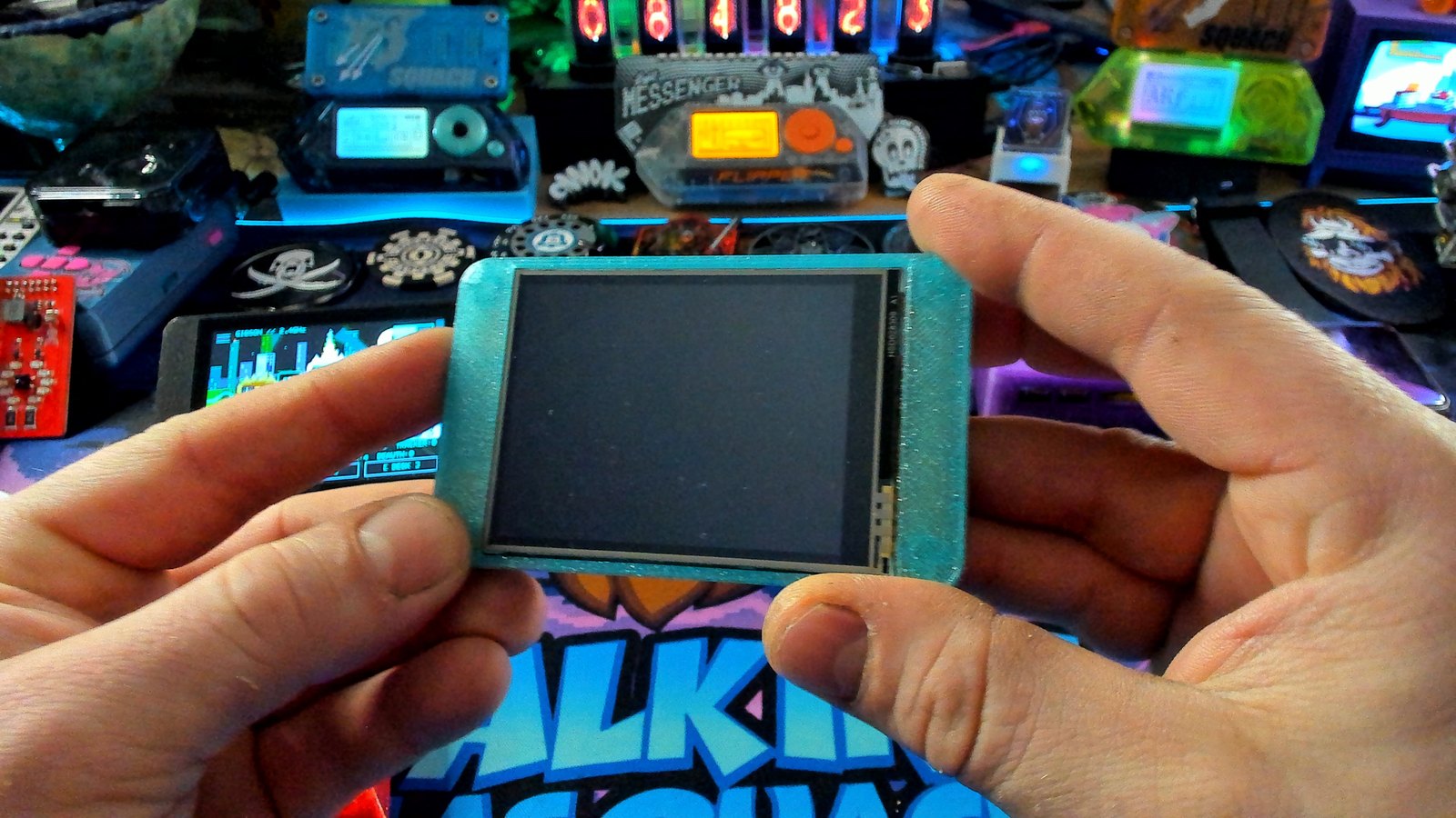
[FIGURE SLOT — Vol 4 §3] The same case from the back, showing whatever openings it provides for the BOOT button, the RGB LED and the microSD slot.
4.3.1 What the firmware needs reachable through the case
Whichever enclosure is used, the firmware gives several of the board’s parts a job, and a case that blocks them takes features away. The table maps each opening to the feature that depends on it.
Table 3 — 3.1 What the firmware needs reachable through the case
| Board part | GPIO | What SquachWatch uses it for | If the case blocks it |
|---|---|---|---|
| USB-C | 1, 3 (console) | Power, flashing, serial console, Set Time & Zone | Board is unusable |
| BOOT button | 0 | Short press: screen off / POCKET MODE; hold ~1 s: CHARGE MODE; hold while plugging in: download mode | No pocket mode; flashing may need the case opened |
| RGB status light | 4, 16, 17 | Idle breathe, alert flashes, unread-message blink, update progress | Lose the at-a-glance status from the back |
| microSD slot | 5 (CS), 18/19/23 | CSV event log (§5) | No SD log; the flash black box still works |
| Light sensor (LDR) | 34 | Listed as in use by the firmware | Not confirmed what a covered LDR changes |
| Speaker pad (P4) | 26 | Listed as in use | The FAQ says the CYDs make no sound |
| Touch panel surface | (XPT2046) | All input | Pressure from a tight bezel can register as touches — recalibrate (§7.2) |
Tip — On the 2.8” CYD the RGB LED is on the back of the board (it is on the front only on the RL Phantom). A case with no window over it hides the one indicator that works with the screen off.
4.4 Power
4.4.1 What the 2.8” CYD offers
The reference board has two power entry points and no battery hardware of its own. The witnessmenow CYD reference lists the connectors as P1 (4-pin: VIN, TX, RX, GND), P3 (GND, IO35, IO22, IO21), CN1 (GND, IO22, IO27, 3.3V) and P4 (speaker, IO26), and notes that “the only power pin on a connector is VIN on P1”; it does not state a voltage for VIN and says nothing about battery power. The project’s own v1.0 design contract is explicit that the CYD has “no battery monitoring”.
   2.8" CYD power entry (connector data: witnessmenow PINS.md)

   USB-C ───────────────┐
                        ├──▶ on-board regulation ──▶ ESP32 + TFT + touch + SD
   P1 VIN (PicoBlade) ──┘        (TFT LDO and ESP32 LDO test pads)

   Battery options — all EXTERNAL to the board:
   ┌──────────────┐                    ┌──────────────────────────┐
   │ USB power    │── USB-C cable ───▶ │ CYD USB-C   (simplest;   │
   │ bank         │                    │ what the FAQ suggests)   │
   └──────────────┘                    └──────────────────────────┘
   ┌──────────────┐  ┌──────────────┐  ┌──────────────────────────┐
   │ 1S LiPo      │─▶│ charger +    │─▶│ CYD USB-C or P1 VIN      │
   │              │  │ 5 V boost    │  │ (voltage on VIN not      │
   └──────────────┘  └──────────────┘  │  documented — verify)    │
                                        └──────────────────────────┘
The project’s own guidance is short: “Most boards run off USB. Plug them into a power bank and off you go.” A power bank on the USB-C port is the zero-risk build. A LiPo with a combined charger and 5 V boost module feeding the USB-C port or P1 VIN is a common hobbyist pattern for this board, but nothing in the SquachWatch repository documents or tests it.
Warning — The VIN rail’s acceptable range is not documented in the sources consulted, and the firmware cannot see a battery on this board. Before wiring a cell to P1, confirm VIN’s regulator and input range against the Sunton schematic (linked from the witnessmenow repository), and do not feed P1 VIN and USB from two different sources at once unless the schematic shows they are isolated. This is general practice, not a project instruction.
4.4.2 What the firmware does about power on a board with no battery sense
Because a CYD cannot read a battery, the firmware substitutes runtime bookkeeping and power-shedding modes:
Table 4 — Because a CYD cannot read a battery, the firmware substitutes runtime bookkeeping and power-shedding modes
| Feature | Where | What it does |
|---|---|---|
| LAST RUN | Settings → SYSTEM | How long the previous power-up lasted. The FAQ calls it “the easiest way to find out what your battery is really worth.” The run is noted every ten minutes, so it is accurate to ten minutes. |
| POWER SAVER | Settings | LOW POWER master switch, SCREEN TIMEOUT, DIM TO, IDLE FRAMES and IDLE AFTER, CPU CLOCK, WAKE ON ALERT. Off by default except on the watch. |
| CHARGE MODE | Settings, or hold BOOT ~1 s | Radios, status light and screen off so a battery charges faster; tap to see elapsed charge time. |
| POCKET MODE | Short press of BOOT | Screen off; a touch will not wake it, only BOOT. Alerts still light it for their card. |
4.4.3 Battery indication by board
For readers building on another supported board, the firmware’s battery support differs sharply. The table is drawn from the board-specific code in src/main.cpp and the pin notes in docs/PINOUT.md.
Table 5 — 4.3 Battery indication by board
| Board | Battery hardware | How the firmware reads it | What the user sees |
|---|---|---|---|
| 2.8” CYD and other plain-ESP32 CYDs | None on the board | Not read | LAST RUN only |
| Freenove ESP32-S3 2.8” (FNK0104B) | 1-cell LiPo on a JST, TP4054 charger | 200K/200K divider to GPIO 9 (ADC1), averaged, voltage-to-percent table | Lava-lamp gauge on the main screen; BATTERY row; “charging” only inferred from the voltage jump |
| Freenove ESP32-S3 3.5” (FNK0104N) | Same arrangement | Divider to GPIO 8 | As above; hold BOOT 3 s is the power switch |
| LilyGo T-Deck Plus | 2000 mAh cell | 1:2 divider on GPIO 4 | As above |
| Marauder V8 (ESP32-C5) | MAX17048 fuel gauge | I²C at 0x36 on SDA 5 / SCL 4 | BATTERY row with ”+” while charging |
| LilyGo T-Watch S3 / S3 Plus | AXP2101 PMU | The PMU’s own percentage and VBUS state | Lava lamp; POWER SAVER on by default |
Note — The Freenove boards’ “charging” indication is a guess: “the charger’s CHRG line goes to an LED rather than a GPIO — so a voltage and an estimate from it, and ‘charging’ only as a guess from the voltage jumping.” On the cable the cell reads the charger’s ~4.2 V.
[FIGURE SLOT — Vol 4 §4] A cased 2.8” CYD running from a small USB power bank, the cable visible, as a portable build.
4.5 The microSD card
4.5.1 Preparation
The card is optional and the firmware treats it that way: “If the card is absent, every call is a silent no-op.” Preparation is one step — format it FAT32 (“If a microSD card is inserted (and FAT32-formatted), every detection is also written to squachwatch-<day>.log”). Card capacity limits and exFAT behaviour are not documented in the repository; the boot log prints the mounted size ([sd] card mounted: N MB), which is the way to confirm a card was accepted.
4.5.2 What lands on the card
Table 6 — 5.2 What lands on the card
| File | When | Content |
|---|---|---|
/squachwatch-YYYYMMDD.log | Clock trusted (NTP, Set Time & Zone, or squad) | One CSV row per detection, one file per local day |
/squachwatch-nodate.log | Clock not yet trusted | Same rows, timestamped in millis() since boot — “because a guessed date can be days behind” |
/wigle-YYYYMMDD-HHMM.csv | cyd-gps build, WARDRIVE on, real fix | WiGLE-format wardrive log, named for the session start in UTC |
The row columns are time, type, rssi, mac, channel, vendor, name, where time is UTC YYYY-MM-DDTHH:MM:SSZ once the clock is trusted; a GPS build appends latitude, longitude and accuracy.
  2.8" CYD — who shares which SPI bus (from include/cyd_user_setup.h, src/sd_log.cpp)

   TFT (ST7789/ILI9341)  MOSI 13  MISO 12  SCLK 14  CS 15  DC 2   ── TFT_eSPI
   Touch (XPT2046)       MOSI 32  MISO 39  SCLK 25  CS 33  IRQ 36 ── own SPI
   microSD               MOSI 23  MISO 19  SCLK 18  CS 5          ── SPI @ 4 MHz
Note —
docs/PINOUT.mdstill lists the TFT data line as MOSI 27 in its first table, while its own “Spare GPIOs” section says 12 and 13 are the display bus and 27 is free on CN1. The compiled-in display header (include/cyd_user_setup.h) uses MISO 12 / MOSI 13 / SCLK 14 with no reset line, which is what the firmware actually drives. Trust the header.
Warning — The DURESS PIN and WIPE AFTER 10 delete the SquachWatch log files from the card as well as from flash. Copy anything worth keeping off the card first.
4.6 The optional GPS module (cyd-gps builds)
4.6.1 Status
Two PlatformIO environments, cyd-gps and cyd-ili9341-gps, add GPS to the 2.8” CYD. They are explicitly “not in the flasher, CI or releases” and the build “Waits for a test on hardware before it ships.” The GPS code came from contributor jotra7’s PR #46 and is the same code the Marauder V8 build uses for its wardriving. Building a GPS CYD therefore means building from source (Vol 6) and accepting an untested configuration.
4.6.2 Wiring
The module is an ATGM336H at 9600 baud. Only its transmit line is used.
Table 7 — 6.2 Wiring
| ATGM336H pin | CYD connection | Connector |
|---|---|---|
| TX | GPIO 35 | P3 |
| VCC | 3.3 V | CN1 |
| GND | GND | CN1 |
| RX | not connected | — |
        ATGM336H                         2.8" CYD
      ┌───────────┐                ┌──────────────────────┐
      │       VCC ├────────────────┤ CN1  3.3V            │
      │       GND ├────────────────┤ CN1  GND             │
      │        TX ├────────────────┤ P3   IO35 (input-only)│
      │        RX ├──  (open)      │                      │
      │   antenna │                │ build: cyd-gps       │
      └───────────┘                │   -DCYD_GPS=1        │
                                   │   CYD_GPS_RX default 35│
                                   └──────────────────────┘
GPIO 35 is input-only on the ESP32, which is why the receive-only arrangement fits it. The default pin is set in code as #define CYD_GPS_RX 35 unless a build overrides it (the T-Deck Plus build uses 44 and the Marauder V8 uses 14).
Note — “The module’s RX is not connected, so the firmware cannot configure the module. It runs on the module’s defaults.” Any module that boots at 9600 baud emitting NMEA should behave the same, but only the ATGM336H is named.
[FIGURE SLOT — Vol 4 §6] An ATGM336H module with its ceramic patch antenna wired to a 2.8” CYD: three PicoBlade leads to P3 (TX→IO35) and CN1 (3.3 V, GND), with the connectors labelled.
4.6.3 Bench-checking the GPS build
The serial console (2,000,000 baud) accepts three GPS commands, which allow the build to be exercised with no module or no sky view:
Table 8 — The serial console (2,000,000 baud) accepts three GPS commands, which allow the build to be exercised with no module or no sky view
| Command | Effect |
|---|---|
GPS FAKE <lat> <lon> | Sets a bench fix, e.g. GPS FAKE -33.857 151.215. Screens and SD rows mark it FAKE; it never sets the clock. |
GPS STATUS | Prints sentence counts, satellites and position. |
GPS OFF | Clears the bench fix. |
WARDRIVE ON | Same as switching WARDRIVE on in Settings. |
With a real fix and WARDRIVE on, the board writes every network and Bluetooth device it hears to /wigle-YYYYMMDD-HHMM.csv; “A bench fix writes nothing. Wardriving pauses when memory runs low, and detection keeps running.”
4.7 First power-on checks
4.7.1 The first-boot sequence
After flashing (Vol 5), the board reboots into a fixed first-boot sequence.
   power / reset
        │
        ▼
   ┌──────────────────────────────────┐  hold a finger on the panel now to
   │ "Hold anywhere now to reset      │──▶ wipe a saved calibration
   │  touch calibration..."  (~1.2 s) │    ("CALIBRATION RESET")
   └──────────────────────────────────┘
        │
        ▼  no saved five-target calibration?
   ┌──────────────────────────────────┐
   │ TOUCH CALIBRATION: 5 targets,    │  boards updating from old firmware
   │ hold each ~1 s, then a check dot │  get SKIP
   └──────────────────────────────────┘
        │
        ▼
   ┌──────────────────────────────────┐
   │ SPLASH (~3 s; ~9 s if a crash    │  version stamp from git describe
   │ card is pending)                 │
   └──────────────────────────────────┘
        │
        ├── first boot ever ──▶ COLOR CHECK: RED / GREEN / BLUE
        │                       INVERT and ORDER until they match, DONE
        ├── newer release known ──▶ SYSTEM PROPERTIES "update is out" window
        ├── was left in desk mode ──▶ DESK
        ▼
   MAIN screen (CLEAR): Squachy, counters, SCAN / LOG / DESK,
   short walkthrough on the first visit
4.7.2 What each check proves
Table 9 — 7.2 What each check proves
| Check | Passes when | If it fails | Fix |
|---|---|---|---|
| Display lights with content | Splash renders | Solid white screen | Wrong display build or 80 MHz too fast — Vol 5 §5.2 |
| Colour check | The word RED is red, etc. | Colours swapped or negative | INVERT / ORDER on the check screen; later via Settings → SYSTEM → CHECK COLORS |
| Touch calibration | Check dot lands under the finger | Taps land elsewhere | Settings → SYSTEM → CALIBRATE TOUCH, or hold a finger on the screen during the reset window |
| Taps register in menus | Short taps act | Slow presses ignored | By design: “A touch held for more than about half a second without moving is ignored” |
| Detection engine running | Counters move after warm-up | ”WiFi: Unknown” / nothing fires | Wait: “~5–10 seconds to warm up after boot” |
| SD card | [sd] card mounted in the boot log | No log file | Reformat FAT32; the rest of the firmware is unaffected |
| Memory health | DIAGNOSTICS shows free heap and largest block | Reboot loop | Note the crash card and DIAGNOSTICS for a bug report |
4.7.3 A first real detection
The build guide’s own acceptance tests:
Table 10 — The build guide's own acceptance tests
| Target | Expected result |
|---|---|
Any BLE device named HC-05 or HC-06 (an old BT speaker or an Arduino module) | SKIMMER counter fires |
| A Wyze, Hikvision or Axis camera | CAMERA row in the LOG |
| A Ring doorbell | RING row in the LOG |
A Flock Safety ALPR, or flock-spoof (github.com/0xD34D/flock-spoof) broadcasting a Flock probe request from a second ESP32 | FLOCK alert |
Tip — Watching the serial console during first boot is worth the trouble: the boot log reports which touch controller answered, the heap after Wi-Fi starts, and the SD mount, all of which narrow down a problem before the UI is even up. On the CYD builds it runs at 2,000,000 baud;
pio device monitor -e cyd-fastpicks that up fromplatformio.ini.
4.8 Cheatsheet updates from this volume
Table 11 — 8. Cheatsheet updates from this volume
| Item | Value |
|---|---|
| Minimum build | ESP32-2432S028R + USB-C data cable; no soldering |
| Case | Not in the repo; launch video points to MakerWorld 3383046 |
| Keep reachable | USB-C, BOOT button (GPIO 0), RGB LED (back of the 2.8”), microSD slot |
| Power on a CYD | USB power bank; no battery sensing → use LAST RUN, POWER SAVER, CHARGE MODE |
| Boards that read a battery | Freenove S3 2.8”/3.5”, T-Deck Plus (ADC), Marauder V8 (MAX17048), T-Watch (AXP2101) |
| SD card | FAT32; /squachwatch-YYYYMMDD.log, CSV time,type,rssi,mac,channel,vendor,name |
| GPS (source builds only) | ATGM336H TX→GPIO 35 (P3), 3.3 V + GND on CN1, RX open, 9600 baud; cyd-gps / cyd-ili9341-gps |
| Console | 2,000,000 baud on CYDs; GPS FAKE lat lon, GPS STATUS, GPS OFF, WARDRIVE ON |
| First boot | calibration → splash → colour check → main screen; allow 5–10 s for detection warm-up |
| Reset touch | hold a finger on the screen during “Hold anywhere now to reset touch calibration…” |
Comments (0)