DSTIKE Hackheld · Volume 2
DSTIKE Hackheld Volume 2 — The ESP8266 Substrate
Tensilica LX106, memory map, GPIO, Wi-Fi monitor mode, packet injection — what works, what doesn't
2.1 Chip-level identity
The Espressif ESP8266 is the part number; EX denotes the bare die-on-tape version, the ESP-12-F and ESP-12-S are common pre-certified modules built around it (chip + 26 MHz crystal + 4 MB SPI flash + EMI shield can + PCB antenna). The Hackheld carries a DSTIKE-branded variant — silkscreen reads “DSTIKE WiFi+ · ESP8266MOD” — that is form-factor compatible with ESP-12 but adds a discrete RF power amplifier in the shielded section. The bonding diagram between the bare die and the module pinout is consistent across all ESP-12-class modules and is what makes the chip “the platform” rather than any one specific board.
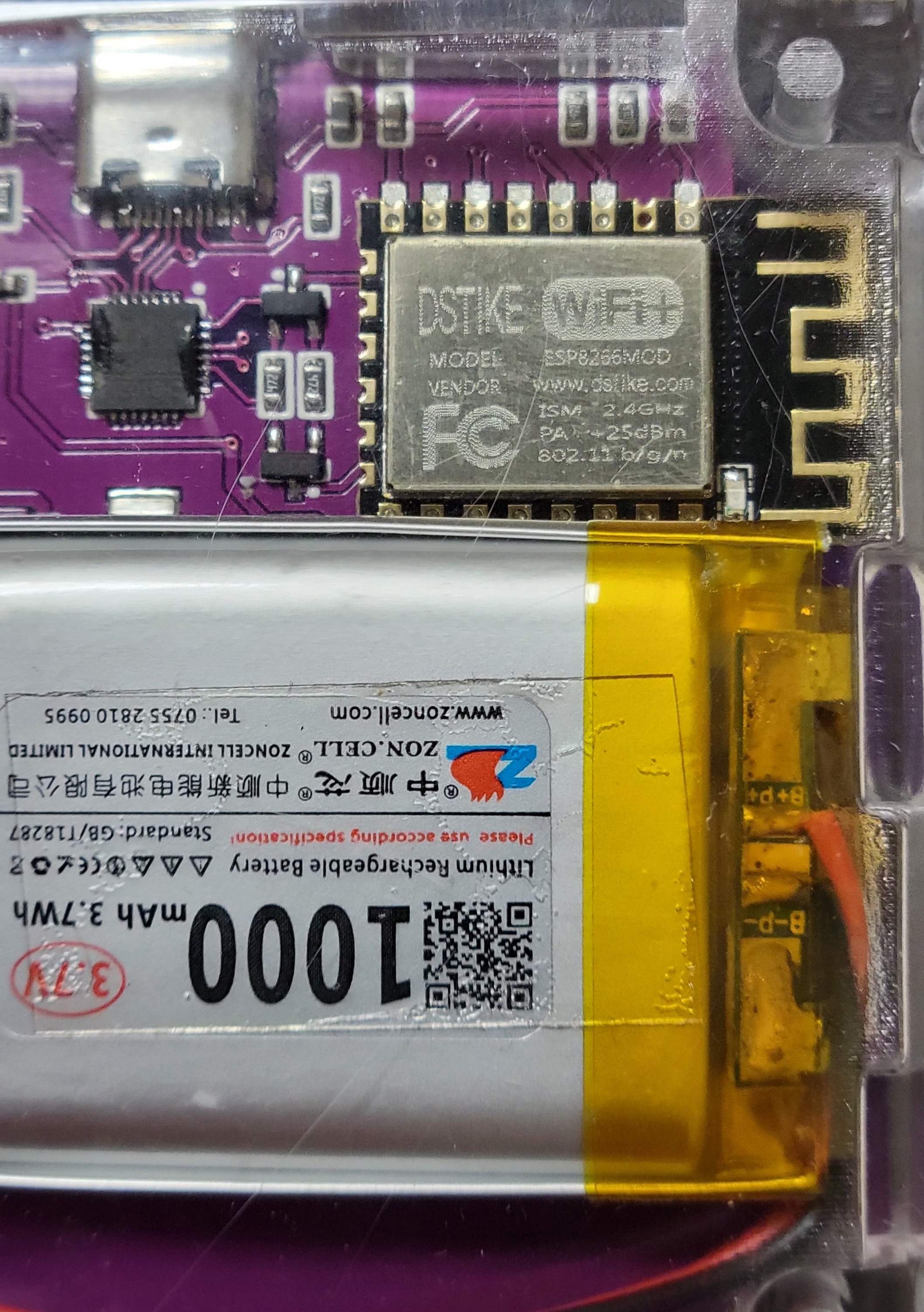
Figure 2.1 — Hackheld V1 back, zoomed on the RF module. Photo, 2026-05-15.
The headline silicon specs:
Table 1 — The headline silicon specs
| Spec | Value |
|---|---|
| Core | Tensilica Xtensa LX106 (32-bit RISC) |
| Clock | 80 MHz default, software-boost-able to 160 MHz |
| RAM (DRAM) | 80 KB usable (32 KB instruction RAM + ~48 KB user data) |
| Wi-Fi | 802.11 b/g/n at 2.4 GHz — no 5 GHz |
| Bluetooth | None — that came with the ESP32 |
| Encryption HW | Hardware AES + SHA accelerators (limited; modern stacks bypass them in favour of software paths) |
| ADC | Single 10-bit ADC, multiplexed to one pin (TOUT, also called A0) |
| GPIO count (chip side) | 17 (GPIO 0..16 + reset/enable) — most module form factors break out only 10–11 |
| Flash | External SPI; 4 MB on this module (the standard ESP-12-F configuration) |
The chip was released in 2014. By 2026 standards it’s old — the comparable modern part is the ESP32-C3 (RISC-V, BLE 5, $1 silicon) or the ESP32-S3 (dual Tensilica LX7 with USB-OTG, BLE 5). But the ESP8266 has not been replaced in Espressif’s catalog — it’s been complemented. The chip is still in production, still cheap, still well-supported by Arduino-ESP8266, and still the right answer for many embedded Wi-Fi tasks.
2.2 Memory map
The ESP8266 has a Harvard-architecture-with-cache memory model that is initially confusing if you’re used to flat-address ARM Cortex MCUs:
Table 2 — The ESP8266 has a Harvard-architecture-with-cache memory model that is initially confusing if you're used to flat-address ARM Cortex MCUs
| Region | Address | Size | What lives here |
|---|---|---|---|
| iRAM0 | 0x40100000 | 32 KB | Code marked IRAM_ATTR (interrupt handlers; tight loops); some early boot code |
| Cache (flash) | 0x40200000 | up to 1 MB cached at a time, from the 4 MB flash | Most of the program code — flash is not execute-in-place beyond what the cache holds; cache misses incur ~3-4 μs penalty |
| dRAM0 | 0x3FFE8000 | 80 KB | All data: stack, heap, BSS, data |
| ROM | 0x40000000 | mask ROM | The boot ROM (UART loader, primary BIOS); cannot be modified by user firmware |
| Peripheral | 0x60000000 | various | Memory-mapped peripherals (GPIO, UART, I²C, SPI, etc.) |
The closed-source Wi-Fi stack reserves ~30 KB of the 80 KB DRAM at all times. What’s left for the user is ~50 KB and in practice ~30–40 KB by the time the Arduino-ESP8266 core’s own globals and the Wire / SPI library buffers are accounted for. Treat 8 KB free heap as the danger-floor below which any Wi-Fi operation (especially DNS, TLS, HTTP) becomes unreliable.
Cache implications for performance: a 32 KB iRAM is small, so most of your code runs from the cached flash region. If a function gets called infrequently, it almost always lives in flash and incurs a cache miss the first time. If a function is called every 100 μs in a tight loop, mark it IRAM_ATTR so it stays in iRAM and the cache pressure on hotter code doesn’t evict it. Vol 11 § Async patterns covers this in working-code form.
2.3 GPIO multiplexing and boot straps
The ESP-12 module breaks out 11 GPIOs (in addition to power, reset, and EN). Each has multiple muxable functions; the Arduino-ESP8266 core picks a sensible default but you can override.
The critical-at-boot pins (don’t ground or pull these the wrong way at reset, or the chip enters a boot mode you didn’t intend):
Table 3 — The critical-at-boot pins (don't ground or pull these the wrong way at reset, or the chip enters a boot mode you didn't intend)
| Pin | Default state at reset | Function |
|---|---|---|
| GPIO 0 | Pull-up by default; ground at reset = enter UART bootloader | The “FLASH” button on the Hackheld pulls this to ground while the chip is held in reset by the RESET button. Together, they enter the ESP8266 ROM bootloader for firmware flashing. |
| GPIO 2 | Pull-up at reset = normal boot | Also commonly the on-module blue LED. Don’t pull this LOW at reset. |
| GPIO 15 | Pull-down at reset = normal boot | Pull this HIGH at reset and the chip enters SDIO boot mode and never starts your program. External I²C bus designers with pull-ups commonly hit this — don’t share a pull-up that lifts GPIO 15 to 3V3 at power-up. |
| EN (CHIP_EN) | Active-high enable for the whole chip | The hardware RESET button on the Hackheld pulses this low. |
The free-to-use pins on the Hackheld (after I²C OLED + buttons + radio):
Table 4 — The free-to-use pins on the Hackheld (after I²C OLED + buttons + radio)
| Available GPIO | Caveat |
|---|---|
| GPIO 3 | Also UART0 RX; can’t use it for general I/O if you also want serial debugging — but if you’re committed to running headless from battery, free |
| GPIO 4, 5 | I²C SDA / SCL — reserved by the OLED |
| GPIO 12, 13, 14, 16 | Likely button inputs on the Hackheld (verify against the matching Spacehuhn firmware A_config.h) |
| GPIO 1 | UART0 TX; freeable in headless mode |
| GPIO 10, 11 | Free on most ESP-12 modules but not exposed on a standard ESP-12-F break-out; check whether DSTIKE routed pads for them |
For custom code that needs more I/O than the Hackheld physically exposes, the standard move is to add an I²C GPIO expander (MCP23017, 16 extra pins) over the same I²C bus the OLED already uses. Vol 11 § GPIO expansion has the working sketch.
2.4 The Wi-Fi radio
Espressif’s ESP8266 radio is a 2.4 GHz 802.11 b/g/n single-stream transceiver. The RF spec on this module (per silk):
- Transmit power: PA = 25 dBm (~316 mW). The bare ESP-12-F’s stock TX power is ~20 dBm (~100 mW); the DSTIKE module’s onboard PA roughly triples the radiated power. Receive sensitivity is governed by the chip’s LNA + the matching network, not the PA — that part is unchanged.
- Channels: 1–14 on the 2.4 GHz ISM band, though channels 12–14 are illegal to transmit on in the US/Canada (regulatory channel set is firmware-configurable; check the regulatory mode active in your build).
- 802.11n: HT20 only, MCS0–7 supported in receive, transmit limited to lower MCS rates. No HT40, no MIMO.
- Frame types the chip can receive: all 802.11 frame types — management, control, data — provided the chip is in promiscuous mode.
- Frame types the chip can transmit raw: limited (see Vol 2 § 6).
The PA = 25 dBm matters for the deauther role specifically. A deauth attack works by repeatedly sending forged deauthentication management frames to a target AP+client pair; the goal is for the target client’s radio to hear the frame. A higher-power TX means a longer effective attack range. Stock ESP-12-F at 20 dBm is good for the same room; PA at 25 dBm extends meaningfully across a small house. Both are well below a serious-Wi-Fi-AP’s 100–200 mW radiated power, and both are subject to the same path-loss math (~6 dB per doubling of distance) — so the practical range improvement is closer to ~40% than to ~3×.
2.5 Monitor mode and packet sniffing
The ESP8266 SDK exposes a promiscuous mode — set via wifi_promiscuous_enable(true) — in which the chip’s radio passes received frames up to a callback function instead of dropping non-targeted ones. This is the equivalent of monitor mode on a Linux wireless interface.
The callback receives a wifi_promiscuous_pkt_t with these fields:
typedef struct {
    signed   rssi:8;      // received signal strength in dBm (signed; -100 = weak, -30 = very strong)
    unsigned rate:4;      // modulation rate
    unsigned channel:4;   // physical channel
    unsigned ...;         // misc PHY fields
    uint8_t  payload[];   // raw 802.11 frame data — variable length
    uint16_t payload_len;
} wifi_promiscuous_pkt_t;
The Spacehuhn firmware’s sniffer is built around this exact callback. So is the Sniffer example in esp8266/Arduino that ships with the core. Custom code that wants to passively observe Wi-Fi traffic — including the WPA-handshake EAPOL exchange, beacon frames, probe requests, etc. — uses this single API.
What you can see in promiscuous mode:
- All beacons in range (the periodic AP advertisements).
- All probe requests in range (clients searching for known SSIDs).
- All probe responses.
- Authentication / association / disassociation / deauthentication frames.
- Data frames, encrypted under WPA2 / WPA3 — you see the encrypted payload, not the plaintext.
- The 4-way EAPOL handshake (which you can capture and later attempt to crack offline on a real computer with
hashcat).
What you can not see:
- 5 GHz traffic (chip can’t tune there).
- Decrypted WPA2/WPA3 payloads — you’d need the PSK plus the capture of the relevant 4-way handshake; decryption is too compute-heavy for the chip to do live.
- Bluetooth / BLE / Thread / Zigbee — different radios entirely.
Channel hopping is implemented in software: set the channel, wait, set another. The Spacehuhn firmware does this 14-channel sweep on the scan tab. Vol 5 § Scanner explains the timing.
2.6 Packet injection — what works, what doesn’t
This is the most consequential ESP8266 fact for the Hackheld’s role. The chip’s RF can receive all 802.11 frame types but transmit only a specific subset via the SDK:
Table 5 — This is the most consequential ESP8266 fact for the Hackheld's role. The chip's RF can receive all 802.11 frame types but transmit only a specific subset via the SDK
| Frame type | Can ESP8266 transmit it raw? | How |
|---|---|---|
| Beacon (AP advertisement) | Yes | wifi_send_pkt_freedom() SDK call. Used for beacon spam attacks. |
| Probe request | Yes | Same API; used for probe-request spam. |
| Probe response | Yes (via SDK trick) | Used for the limited “evil twin”-style work the Spacehuhn fork implements. |
| Deauthentication | Yes | The headline feature — see §7 below. |
| Association / Authentication | No (raw) | Generated only as part of the legitimate Wi-Fi state machine when the chip acts as a STA. |
| Data frames | No raw injection. | The SDK does not expose a path to put arbitrary data frames on the air. This is the limitation that distinguishes ESP8266 from a Linux laptop with a real monitor-mode-capable Wi-Fi adapter. |
The reason for the limit is that the closed-source Wi-Fi blob handles the data path through its own state machines (encryption, sequence numbers, retransmits, etc.) and the SDK doesn’t expose a raw frame-emit hook for those. The “freedom packet” SDK function — discovered by Spacehuhn’s reverse-engineering circa 2017 — is intended for arbitrary management-frame emit and happens to also emit deauth frames cleanly.
For attacks that require data-frame injection — e.g., a true man-in-the-middle, ARP-poison-style, or anything that needs to spoof a connection’s payload — the Hackheld is not the right platform. A Raspberry Pi + an Alfa AWUS036ACM adapter or any laptop with a CFM-mode Wi-Fi card is.
2.7 Why deauth is special
The 802.11 deauthentication frame is a management frame that says, in effect: “the station with MAC xx:xx:xx:xx:xx:xx is being kicked off this AP.” It is part of the legitimate protocol — APs send these when their config changes; clients send these when they leave.
Critically, deauth frames in WPA2 and earlier were not authenticated. Anyone could forge a deauth claiming to be from the AP and the targeted client would treat it as legitimate, immediately tear down the association, and try to reconnect. Send a stream of these and you’ve created a denial-of-service against that AP-client pair. Send them targeting broadcast MAC ff:ff:ff:ff:ff:ff and you’ve denied service to every client on that AP.
This is why deauth attacks were the headline use of every “evil twin” / “wifite” / “aircrack-ng” toolkit for a decade: the unauthenticated deauth was the universal reset button on someone else’s Wi-Fi.
In WPA3 and in 802.11w (Management Frame Protection / MFP) when WPA2 networks negotiate it, management frames are authenticated. A forged deauth from a different MAC simply gets ignored. Most enterprise Wi-Fi deployed after ~2020 negotiates MFP. Most consumer Wi-Fi as of 2026 is still WPA2-Personal with MFP-disabled, especially older routers. The Hackheld’s deauth is thus very effective against the long tail of home networks and old enterprise installs, and very ineffective against modern enterprise.
Legal note (full treatment in Vol 12 § Legal): a deauth attack against a Wi-Fi network you do not own is a denial-of-service attack and is illegal in virtually every jurisdiction. The fact that the underlying protocol is weak does not legalise the exploit. The Hackheld is a lab tool — operate it against your own equipment or with explicit written authorization, period.
2.8 Power profile
Approximate current draw on the Hackheld (estimated from datasheet + DSTIKE module typical numbers; verify on the bench):
Table 6 — Approximate current draw on the Hackheld (estimated from datasheet + DSTIKE module typical numbers; verify on the bench)
| State | Current at 3.7 V | Hours from 1000 mAh |
|---|---|---|
| Deep sleep (chip only; no buttons; OLED off) | 20 μA | 50,000 hours / 5.7 years (the LiPo self-discharges first) |
| Modem sleep (Wi-Fi off; CPU running; OLED on) | 15 mA | 67 |
| Light sleep | 1 mA | 1,000 |
| Wi-Fi STA, idle connected | 20 mA | 50 |
| Wi-Fi STA, active TX | 80 mA average; 300 mA peak during TX bursts | 12 |
| Wi-Fi SoftAP, idle | 50 mA | 20 |
| Deauth attack (continuous TX at PA = 25 dBm) | 250–300 mA average | 3–4 |
In practice, the binding-constraint on real-world use is the Wi-Fi scan + attack mix typical of the Deauther firmware, which averages ~150–200 mA. The 1000 mAh battery gives ~5–7 hours of typical use. Vol 4 § Battery has the full charge / discharge cycle.
2.9 The closed-source Wi-Fi blob
A historical aside that’s worth knowing if you read any old ESP8266 dev forums: the Wi-Fi MAC + PHY firmware on the ESP8266 is not open source. It’s distributed by Espressif as a binary blob that the SDK links against. Stefan Kremser’s Deauther was the first widely-used artifact built by reverse-engineering the blob’s internal SDK to find a raw-frame-transmit hook — Espressif officially didn’t support it, but didn’t break it either (a tradition continued in later ESP32 stacks).
The blob has been incrementally documented over the years by community efforts (the esp8266-nonos-sdk repo, the esp-open-rtos work, the Sming framework). For most custom-firmware work, you treat the blob as a fixed substrate — call its APIs (wifi_set_macaddr, wifi_promiscuous_enable, wifi_send_pkt_freedom, etc.), don’t try to modify it.
2.10 Where the chip falls short
A summary list, to set realistic expectations for the rest of this series:
- 2.4 GHz only. No 5 GHz, no 6 GHz. Roughly half the Wi-Fi spectrum on a modern home network is invisible to this device.
- No BLE. No iBeacon scanning, no BLE attack, no Bluetooth Classic. The Flipper WiFi Devboard (also a 2.4 GHz device) is no better — both are ESP-something but BLE is on ESP32, not ESP8266 or ESP32-S2.
- No raw data-frame injection. Limits attack repertoire to deauth / beacon-spam / probe-spam / evil-twin-as-AP. No CFM-mode ARP-poison, no true MITM at the data layer.
- 80 KB DRAM is tight. A custom firmware with a fancy web UI + complex menu system + persistent storage will hit memory pressure faster than developers expect.
- No FPU. Floating-point math is software-emulated and slow. Use fixed-point or integer math in hot loops.
- Single ADC pin with 0–1 V (not 0–3.3 V) input range, multiplexed with the VCC sense — meaning you typically use it for only one thing in a given build (either reading an external voltage or the chip’s own supply, not both).
- WPA-handshake capture is possible; cracking is not. The chip lacks the CPU and the RAM to run hashcat-grade compute.
These are real limits, not artificial ones. For everything they exclude, the lineup has alternatives — see Vol 12 § Comparison for the full decision matrix.
2.11 What’s next
→ Vol 3 — Board hardware walkthrough unpacks every physical component on the Hackheld unit, photo-driven, top to bottom. The DSTIKE WiFi+ module, the SSD1306 OLED, the 7-button cluster, the CH340 USB-to-serial, the TP4056-class charger, the LiPo cell. Specs, supply chain, replacement parts where applicable.
Comments (0)