Nyan Box · Volume 2
Nyan Box Volume 2 — Hardware
ESP32-WROOM-32U, the OLED, the power subsystem, EEPROM, the four-antenna layout, the printed enclosure — schematic-block depth
2.1 About this volume
Vol 2 walks the nyanBOX hardware at schematic-block depth — everything except the three NRF24 radios, which get their own volume (Vol 3) because the triple-radio arrangement is the device’s distinctive engineering feature.
Spec provenance: vendor-sourced (nyandevices.com), not bench-verified. Where a value depends on measurement, it’s flagged as estimate.
[FIGURE SLOT — Vol 2, § 1] PCB top-side photo showing the ESP32-WROOM-32U, the three NRF24 modules, the OLED ribbon, and the four U.FL connectors. Source: vendor product page or a community teardown. Caption when filled: “Figure 2.4 — nyanBOX PCB, top side.”
[FIGURE SLOT — Vol 2, § 1] PCB bottom-side photo (likely battery + EEPROM side). Source: same. Caption when filled: “Figure 2.5 — nyanBOX PCB, bottom side.”
2.2 Block diagram
   nyanBOX — Hardware Block Diagram
   ════════════════════════════════════════════════

   USB-C ──┬──→ Charge controller (TP4056-class)
           │         │
           │         └──→ 2500 mAh LiPo ──→ 3.3V reg ──→ system rail
           │
           └──→ USB-Serial (CDC or CP2102-class) ──→ ESP32 UART0


              ┌──────────────────────────────────┐
              │   ESP32-WROOM-32U                │
              │   dual-core 240 MHz Xtensa LX6   │
              │   Wi-Fi 2.4 GHz + BT 5.0         │
              │   U.FL antenna  ──────────────┐  │
              └──┬────┬────┬────┬────┬────┬────┼──┘
                 │    │    │    │    │    │    │
        I²C ─────┘    │    │    │    │    │    └──→ [ESP32 antenna]
         │            │    │    │    │    │
         ▼            │    │    │    │    └──→ EEPROM (I²C, shared bus)
   ┌──────────┐       │    │    │    │
   │ OLED     │       │    │    │    └──→ Arrow-key GPIO matrix
   │ SSD1306  │       │    │    │
   │ 128×64   │       │    │    └──→ SPI bus (shared) ──┐
   └──────────┘       │    │                            │
                      │    │         ┌──────────────────┴──────┐
                      │    │         │  3× NRF24L01+ GTmini     │
                      │    │         │  (CE/CSN per radio;      │
                      │    │         │   SCK/MOSI/MISO shared)  │
                      │    │         │  → see Vol 3             │
                      │    │         └──┬────┬────┬─────────────┘
                      │    │            │    │    │
                      │    │      [NRF #1][NRF #2][NRF #3] antennas
                      │    │
                      │    └──→ Status LED(s)
                      │
                      └──→ Battery-voltage ADC (fuel gauge estimate)
The architecture is conventional ESP32-handheld fare with one twist: the SPI bus fans out to three NRF24 radios instead of one. Vol 3 covers exactly how that’s wired and why it matters.
2.3 ESP32-WROOM-32U — the brains
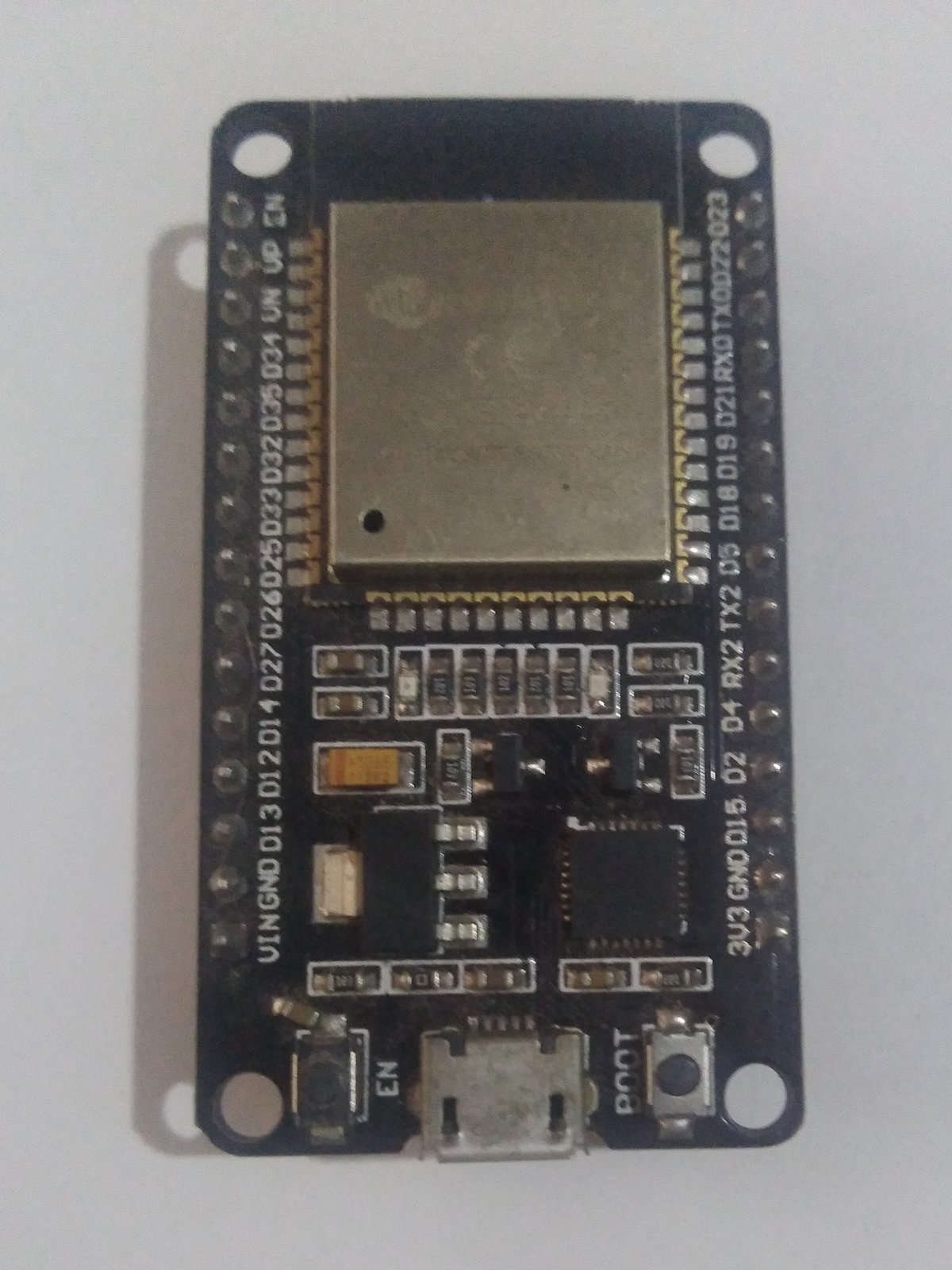
Figure 2.1 — ESP32 SoC (representative). Photo: File:ESP32.jpg. Via Wikimedia Commons.
2.3.1 The module
Table 1 — 3.1 The module
| Aspect | Value | Notes |
|---|---|---|
| Module | ESP32-WROOM-32U | The “U” = U.FL external-antenna connector variant |
| SoC | ESP32-D0WD (or -D0WDQ6) | Dual-core Xtensa LX6 |
| Clock | 240 MHz (configurable down) | |
| SRAM | 520 KB | On-chip |
| Flash | 4 MB (typical for WROOM-32U) | SPI flash in-module |
| PSRAM | None | WROOM-32 family has no PSRAM (that’s WROVER) |
| Wi-Fi | 802.11 b/g/n, 2.4 GHz | |
| Bluetooth | v5.0 — BR/EDR (Classic) + BLE | The original ESP32 has both Classic and LE |
| Antenna | U.FL connector → external stub | The “-U” variant; better RF than the PCB-antenna WROOM-32 |
| GPIO | ~34 usable (minus strapping + flash pins) | Enough for OLED + 3× NRF24 + keys + EEPROM |
2.3.2 Why the “-U” variant matters
The plain ESP32-WROOM-32 has a PCB trace antenna. The -U variant routes the RF to a U.FL connector instead, letting Nyan Devices fit an external stub antenna. For a multi-radio device this is the right call:
- Better Wi-Fi/BT range than a trace antenna
- Physical separation from the three NRF24 antennas (reduces coupling — see § 6)
- Field-replaceable antenna if one breaks
2.3.3 What the ESP32 silicon enables on the nyanBOX
- Wi-Fi 2.4 GHz — the entire Vol 4 Wi-Fi toolset; promiscuous-mode monitor, beacon injection, deauth
- BT Classic + BLE — BLE scan/spoof, BT Classic scan (the original ESP32 still has Classic, unlike the S3)
- RemoteID decode — RemoteID broadcasts over Wi-Fi (Beacon/NAN) and BT (Legacy/Long-Range); the ESP32’s dual-mode radio is exactly what’s needed (Vol 6)
- SPI master — drives the three NRF24 radios (Vol 3)
- I²C master — OLED + EEPROM share the I²C bus
- The 40+ tool firmware — dual-core 240 MHz with 520 KB SRAM is comfortably enough for the menu-driven firmware
2.3.4 What the ESP32 silicon does NOT have
Table 2 — 3.4 What the ESP32 silicon does NOT have
| Missing | Consequence |
|---|---|
| 5 GHz Wi-Fi | nyanBOX is 2.4 GHz only — hard scope limit |
| Native USB (it’s a -32, not an -S3/-C3) | USB-C goes through a USB-serial bridge chip, not native CDC |
| PSRAM | Limits large-buffer operations; fine for this firmware |
| BLE 5 Long Range coded PHY full support | ESP32 (original) BLE is 5.0 but coded-PHY support is limited vs ESP32-C3/S3 — relevant for some RemoteID BT Long Range frames (Vol 6 § 5) |
The original-ESP32 choice (vs ESP32-S3 like the Game Over uses) is notable. Likely reasons: cost, the BT Classic capability the original ESP32 has, and that the firmware predates a port to newer silicon. The practical cost: no native USB, no PSRAM, slightly weaker BLE-5 coded-PHY.
2.4 The OLED display
Table 3 — 4. The OLED display
| Aspect | Value | Notes |
|---|---|---|
| Size | 0.96” diagonal | The ubiquitous small-OLED size |
| Resolution | 128 × 64 pixels | Monochrome |
| Controller | SSD1306-class (likely) | I²C interface; verify on hardware |
| Interface | I²C (shared bus with EEPROM) | 2-wire; address typically 0x3C |
| Colors | Monochrome (white-on-black or blue-on-black) | Single-color OLED |
| Refresh | Adequate for menu UI + simple graphs | Not video-class |
2.4.1 What 128×64 monochrome can show
   ┌────────────────────────────────┐
   │ WiFi Scan          [batt 87%]  │   ← status line
   ├────────────────────────────────┤
   │ > NETGEAR_5A      -42 dBm  ch6 │
   │   xfinitywifi     -61 dBm  ch1 │   ← scrollable list
   │   [hidden]        -70 dBm  ch11│
   │   IoT_Camera_3F   -55 dBm  ch6 │
   ├────────────────────────────────┤
   │ [OK] details  [←] back         │   ← action hints
   └────────────────────────────────┘

   128×64 fits ~8 lines of 6×8 text, or
   ~5 lines of larger text + a status bar + action hints.
   Enough for menus, scan lists, simple bar-graph spectrum,
   and the XP-progression UI.
2.4.2 The display as a constraint
128×64 monochrome is a real constraint on the UX. The nyanBOX firmware’s menu-driven design isn’t just a philosophy choice — it’s partly forced by the display. You can’t show a rich waterfall or a dense data table on 128×64; you show a menu, a list, a simple bar graph. The education-first UX and the small OLED are mutually reinforcing design choices.
[FIGURE SLOT — Vol 2, § 4] Photo of the OLED showing a live tool screen (Wi-Fi scan list or the RemoteID watch). Source: vendor product page. Caption when filled: “Figure 2.6 — The 0.96” OLED running [tool].“
2.5 Power subsystem
2.5.1 The power tree
   USB-C 5V Vbus
        │
        ├──→ Charge controller (TP4056 / MCP73831-class)
        │         │
        │         └──→ 2500 mAh LiPo cell + protection IC
        │                   │
        └───────────────────┴──→ 3.3V regulator ──→ system rail
                                       │
                                       ├──→ ESP32-WROOM-32U
                                       ├──→ 3× NRF24L01+ (3.3V; NRF24 is 3.3V-only)
                                       ├──→ OLED
                                       ├──→ EEPROM
                                       └──→ status LEDs
2.5.2 Battery — 2500 mAh is generous
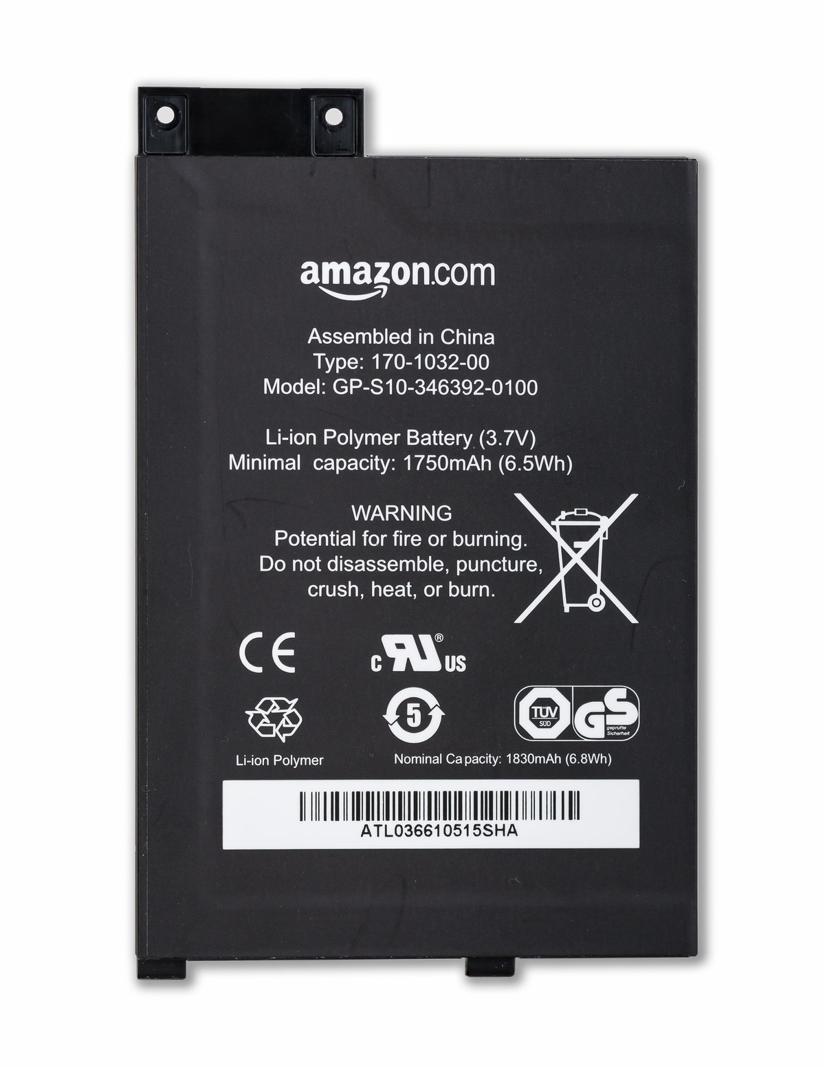
Figure 2.2 — LiPo pouch cell (representative). Photo: File:Kindle-Reader Lithium-Polymer-Battery-01.jpg by CEphoto, Uwe Aranas. License: CC BY-SA 3.0. Via Wikimedia Commons.
Table 4 — 5.2 Battery — 2500 mAh is generous
| Aspect | Value | Notes |
|---|---|---|
| Capacity | 2500 mAh | Generous for the form factor — bigger than Flipper’s 2000, much bigger than a Cardputer |
| Chemistry | LiPo, single cell (3.7V nominal) | Standard |
| Charge | USB-C, ~1 A (TP4056-class) | ~2.5-3 h full charge |
| Energy | ~9.25 Wh | Reference for runtime planning |
| Protection | DW01/FS8205A-class protection IC (typical) | Over/under-voltage, over-current |
| Fuel gauge | ADC voltage estimate (likely) | Not a coulomb-counter; % is approximate |
2.5.3 Estimated current draw
These are engineered estimates — the NRF24 + ESP32 combination is well-characterized, but bench-verify on the actual unit:
Table 5 — These are engineered estimates — the NRF24 + ESP32 combination is well-characterized, but bench-verify on the actual unit
| Mode | Estimated current | Notes |
|---|---|---|
| Idle (OLED on, radios off) | ~60-90 mA | ESP32 idle + OLED |
| Wi-Fi scan | ~120-180 mA | ESP32 radio active |
| 1× NRF24 RX | +13-15 mA | Per NRF24 in RX |
| 3× NRF24 RX simultaneous | +40-45 mA | All three radios listening (Vol 3) |
| NRF24 TX burst | +11-12 mA per radio (per burst) | NRF24 TX is brief + low-power |
| Wi-Fi TX (deauth/beacon) | ~200-280 mA | ESP32 TX bursts |
| Everything on (Wi-Fi + 3× NRF24) | ~250-320 mA | Heaviest realistic load |
2.5.4 Estimated runtime
Against the 2500 mAh cell (~2200 mAh usable after cutoff margin):
Table 6 — Against the 2500 mAh cell (~2200 mAh usable after cutoff margin)
| Mode | Est. current | Est. runtime |
|---|---|---|
| Idle (display on) | 75 mA | ~29 hours |
| Wi-Fi scan continuous | 150 mA | ~14.5 hours |
| 3× NRF24 RX (multi-channel sniff) | 115 mA | ~19 hours |
| RemoteID watch (Wi-Fi + BT monitor) | 160 mA | ~13.5 hours |
| Camera sweep (2.4 GHz monitor) | 130 mA | ~17 hours |
| Heaviest (Wi-Fi TX + 3× NRF24) | 290 mA | ~7.5 hours |
The 2500 mAh cell makes the nyanBOX a genuine all-day device for passive work — RemoteID watch and camera sweep both run 13-17 hours on a charge. That’s a real advantage for the device’s intended detection use cases (Vol 6, Vol 7), which are inherently long-dwell.
2.5.5 Charge-while-operating
Standard topology — USB-C feeds the charger + system simultaneously. The nyanBOX can run indefinitely on USB-C power; useful for fixed-position RemoteID watch or camera-sweep deployments.
2.6 Antenna layout — four radios, four antennas
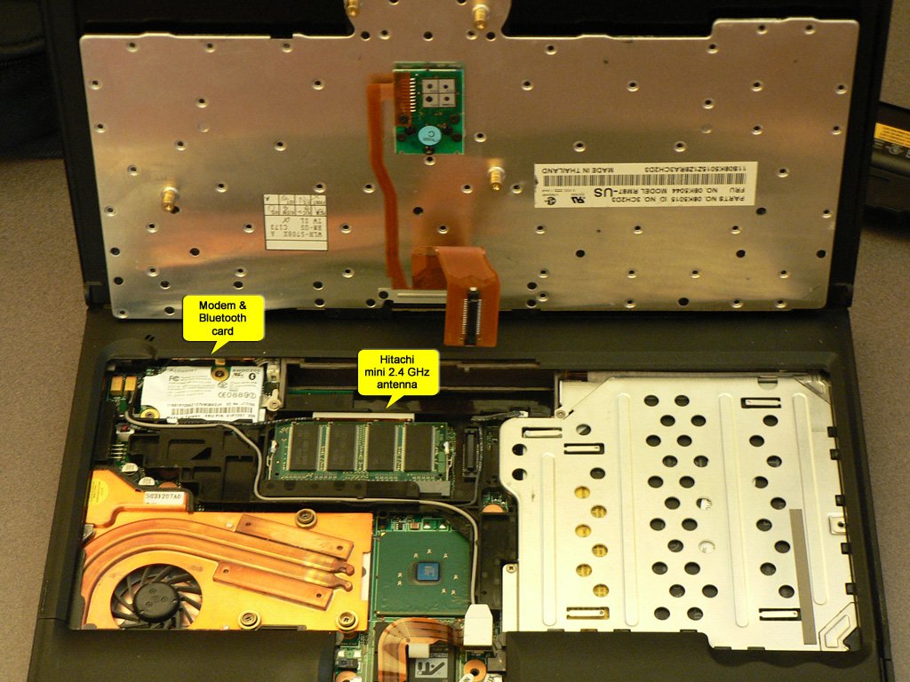
Figure 2.3 — 2.4 GHz antenna (representative). Photo: File:ThinkPad T41 showing mini 2.4 GHz antenna.jpg by Jnavas1. License: CC BY-SA 3.0. Via Wikimedia Commons.
The nyanBOX has four 2.4 GHz radios (1× ESP32 + 3× NRF24) and four antennas — one each. This is the part of the hardware design that needs the most care, because four 2.4 GHz antennas in a handheld enclosure want to couple into each other.
   Antenna layout (hypothesized — verify on unit)
   ═══════════════════════════════════════════════

        [ESP32 ant]              [NRF#1 ant]
              \                      /
               \                    /
                \   ┌──────────┐   /
                 \  │          │  /
                  \ │  nyanBOX │ /
                   \│   PCB    │/
                    │          │
                   /│          │\
                  / │          │ \
                 /  └──────────┘  \
                /                  \
        [NRF#2 ant]              [NRF#3 ant]

   Four stub antennas, ideally one per corner / edge,
   spaced to minimize mutual coupling.
2.6.1 The coupling problem
Four antennas all operating in 2.400-2.485 GHz, inches apart, in the same plastic box:
- TX leakage — when one radio transmits, the others’ front-ends see it. NRF24 RX can be desensitized or even damaged by a strong nearby TX (NRF24’s max input is ~0 dBm before damage risk).
- Reduced effective isolation — the whole point of 3× NRF24 is independent channels; coupling erodes that independence.
- MIMO-ish leakage — the DEVELOPMENT.md note flags this directly: “Three antennas at 2.4 GHz means MIMO-ish leakage. Keep antennas spaced or you’ll get coupling that reduces effective isolation.”
2.6.2 Mitigations in the design
What Nyan Devices likely does (and what to verify):
Table 7 — What Nyan Devices likely does (and what to verify)
| Mitigation | Why | Verify on unit |
|---|---|---|
| Physical spacing | Distance is the cheapest isolation | Antennas at corners/edges, not clustered |
| Antenna orientation | Cross-polarization reduces coupling | Some antennas perpendicular? |
| The ESP32 on U.FL | Lets the ESP32 antenna be placed away from the NRF24 cluster | The “-U” variant choice (§ 3.2) |
| Firmware-side TX/RX coordination | Don’t TX on one radio while another is doing sensitive RX | Vol 3 § 4 |
2.6.3 Practical implication
For the user: antenna placement matters. If the four antennas are foldable/positionable, spreading them out improves multi-radio isolation. Clustering them (e.g., all folded flat for pocket carry) degrades the 3× NRF24 independence that’s the device’s hardware selling point. Vol 3 § 5 covers this from the radio-performance angle.
[FIGURE SLOT — Vol 2, § 6] Photo of the nyanBOX showing the four-antenna layout and how they’re positioned on the enclosure. Source: vendor product page. Caption when filled: “Figure 2.7 — The four-antenna layout.”
2.7 EEPROM + state persistence
The nyanBOX uses an EEPROM (not microSD, unlike the Game Over) for persistent state.
Table 8 — 7. EEPROM + state persistence
| Aspect | Value | Notes |
|---|---|---|
| Type | I²C EEPROM (24-series likely; e.g. 24LC256) | Shares the I²C bus with the OLED |
| Capacity | Small — KB-class, not MB | EEPROM, not flash storage |
| What it stores | Settings + XP-progression state | The gamification persists here |
| What it does NOT store | Capture logs, large data | No room — that’s the microSD’s job on other devices |
2.7.1 The capture-storage limitation
Because the nyanBOX has EEPROM rather than microSD, it can’t store large capture logs on-device. This is a real limitation vs the Game Over (which has microSD):
- Scan results, sniffed packets, RemoteID logs, camera-detection hits — these are shown on the OLED and held in RAM, not written to a card
- Long-dwell detection sessions (a multi-hour RemoteID watch) can’t log everything to disk for later analysis
- To preserve data, you either read it off the OLED in real time, or pull it over USB-serial to a host (Vol 9 § 4)
2.7.2 XP-state persistence
The one thing the EEPROM definitely persists is the XP-progression state. The gamification survives power cycles. Note from DEVELOPMENT.md: re-flashing the firmware resets the XP state — if you care about preserving progression, back up the EEPROM contents first (vendor may publish a backup tool). The XP state is not precious for an experienced user; but it’s worth knowing the re-flash behavior.
2.8 Input — the arrow-key cluster + device lock
2.8.1 The input hardware
The nyanBOX UI is driven by an arrow-key cluster — up/down/left/right + an OK/select. Likely a tactile-button matrix on GPIO. No QWERTY (unlike a Cardputer), no joystick (unlike the Game Over) — just directional navigation.
   Input layout
   ════════════
            [ ↑ ]
       [ ← ][OK][ → ]
            [ ↓ ]

   5 inputs. Menu navigation: arrows move,
   OK selects, (likely) ← or a long-press backs out.
   That's the entire UI vocabulary — and it's
   sufficient for a menu-driven 40-tool catalog.
2.8.2 The device-lock feature
The nyanBOX has an arrow-sequence device lock — enter a directional sequence on the OLED to unlock the device. This is a deliberate design choice tied to the education-first positioning (§ Vol 1 § 4.3):
- Not security-grade — a directional sequence has a tiny keyspace; this is not encryption
- It’s a “guard rail” — keeps a curious bystander (a student, a kid, a passerby) from triggering a disruptive tool
- Relevant because the target user lends the device — education/demo use means the nyanBOX gets handed around
The device lock is a minor convenience, not a feature that drives the buy decision. Worth knowing it exists; worth setting it if the device is ever carried somewhere it might be handled by others.
2.9 The printed enclosure
The nyanBOX ships in a printed (3D-printed) enclosure. This is consistent with the small-vendor, community-rooted nature of Nyan Devices.
Table 9 — 9. The printed enclosure
| Aspect | Likely value | Notes |
|---|---|---|
| Material | PLA or PETG (typical for printed enclosures) | PETG is more heat/impact tolerant |
| Construction | Multi-part, screwed or snap-fit | |
| Antenna mounts | Four U.FL → external stub passthroughs | |
| Ports | USB-C cutout | |
| Durability | Moderate — printed plastic, not injection-molded | Treat gently vs an injection-molded commercial product |
| Repairability | High — printed parts can be re-printed | A small-vendor advantage |
2.9.1 Practical implications
- It’s a printed enclosure, not a ruggedized one — fine for bench, education, careful field use; not a throw-in-a-toolbag device
- The printed nature is a feature for repairability — if a part cracks, the vendor (or you) can re-print it
- No IP rating — keep it dry
[FIGURE SLOT — Vol 2, § 9] Photo of the assembled enclosure from multiple angles showing the printed construction, port cutouts, and antenna passthroughs. Source: vendor product page. Caption when filled: “Figure 2.8 — The printed enclosure.”
2.10 Thermal
The nyanBOX’s thermal load is modest — it’s a low-power 2.4 GHz device, not an RF power amplifier.
Table 10 — 10. Thermal
| Heat source | Dissipation | Notes |
|---|---|---|
| ESP32-WROOM-32U | ~0.5-0.8 W at full Wi-Fi load | The dominant heat source |
| 3× NRF24L01+ | ~0.15 W total (RX); brief TX spikes | NRF24 is very low-power |
| 3.3V regulator | Small loss | Linear or buck |
| OLED | Negligible |
Total worst-case: ~1 W. In a printed plastic enclosure with no active cooling:
- Steady-state: case warms slightly (~5-10 °C above ambient) under continuous Wi-Fi work
- No thermal throttling concern — the nyanBOX never gets near a thermal limit
- Battery thermal — the 2500 mAh cell barely warms at these currents
Thermal is not a meaningful operational constraint for the nyanBOX. This contrasts with, e.g., the PortaRF (a HackRF-class TX device where sustained TX is genuinely thermal-limited). The nyanBOX’s low-power 2.4 GHz nature means you can run it continuously without thermal concern.
2.11 Resources
Datasheets
- ESP32-WROOM-32U: https://www.espressif.com/sites/default/files/documentation/esp32-wroom-32u_datasheet_en.pdf
- NRF24L01+: https://www.nordicsemi.com/Products/NRF24L01P (Vol 3 covers in depth)
- SSD1306 OLED controller: Solomon Systech product page
- 24LC256-class I²C EEPROM: Microchip product page
- TP4056 charge controller: NanJing TopPower
Vendor
- Nyan Devices: https://nyandevices.com
- Vendor GitHub (docs): linked from the site
Sibling reference
- Ruckus Game Over deep dive (the sibling hardware-class reference):
End of Vol 2. Next: Vol 3 is the triple-NRF24 subsystem deep dive — the SPI bus arrangement, the parallel-channel theory, transmit-and-confirm, signal-strength triangulation, and the antenna-isolation reality.
Comments (0)