Nyan Box · Volume 3
Nyan Box Volume 3 — The Triple-NRF24 Subsystem
Why three radios, the shared-SPI-bus arrangement, parallel-channel sniffing, transmit-and-confirm, RSSI triangulation, the antenna-isolation reality
3.1 About this volume
The triple-NRF24 arrangement is the single most distinctive piece of engineering in the nyanBOX. Almost every ESP32+NRF24 board on the market has one NRF24. The nyanBOX has three — and that turns a single-channel time-slicing radio into a genuine parallel-channel instrument.
In order: what one NRF24 does (§ 2), why three changes the game (§ 3), how they’re wired (§ 4), the antenna-coupling reality that limits the benefit (§ 5), and the three operating modes the triple arrangement enables (§ 6-8).
This is an engineer-grade volume — it assumes you want the SPI-timing and RF-isolation detail, not a marketing summary.
3.2 The NRF24L01+ — what one radio does
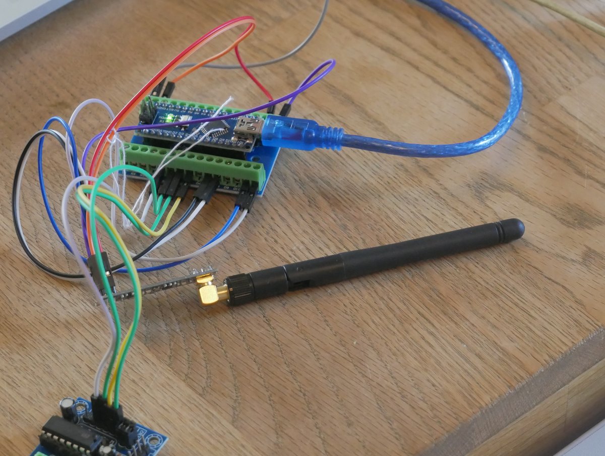
Figure 3.1 — NRF24L01+ module (representative). Photo: File:Tüftlerclub nRF24L01 Test.jpg by ChristianSW. License: CC0. Via Wikimedia Commons.
The Nordic NRF24L01+ is a 2.4 GHz GFSK transceiver — the workhorse radio of cheap wireless mice, keyboards, drones, RC toys, and a thousand IoT gadgets.
3.2.1 NRF24L01+ key specs
Table 1 — 2.1 NRF24L01+ key specs
| Parameter | Value | Notes |
|---|---|---|
| Frequency | 2.400 - 2.525 GHz | 125 possible 1-MHz channels (0-124); +1 MHz step |
| Modulation | GFSK | Gaussian frequency-shift keying |
| Data rates | 250 kbps / 1 Mbps / 2 Mbps | Selectable |
| TX power | -18 / -12 / -6 / 0 dBm | 0 dBm max on the bare module; PA-LNA variants reach ~+20 dBm |
| RX sensitivity | ~-94 dBm (at 1 Mbps) / ~-104 dBm (at 250 kbps) | Lower rate = better sensitivity |
| Interface | SPI (up to 10 MHz) | Plus CE (chip-enable) and IRQ pins |
| Supply | 1.9 - 3.6 V | 3.3 V — NOT 5 V tolerant |
| RX current | ~13.5 mA (2 Mbps) | Low-power |
| TX current | ~11.3 mA (0 dBm) | Low-power, brief |
| Addressing | 3-5 byte configurable address | Up to 6 RX “pipes” per radio |
| Channels | 126 (0-125), 1 MHz spacing | Channel N = 2400 + N MHz |
3.2.2 The “GTmini” variant
The nyanBOX uses NRF24L01+ GTmini modules — a compact form-factor variant of the standard NRF24L01+ breakout. Functionally identical silicon; the “GTmini” is just a smaller PCB layout. (The “+PA+LNA” long-range variants are physically larger; the GTmini is the small one — so the nyanBOX’s NRF24s are likely the bare ~0 dBm type, not the +20 dBm PA-LNA type. Verify on hardware — it matters for TX range.)
3.2.3 The single-radio limitation
One NRF24 can only listen to one channel at a time. To monitor multiple channels, a single-radio device must time-slice — hop channel 75, listen 50 ms, hop 76, listen 50 ms, hop 77, listen 50 ms, repeat. The problem:
   Single NRF24 — time-slicing 3 channels
   ═══════════════════════════════════════

   ch75 │████░░░░░░░░████░░░░░░░░████░░░░░░░░│
   ch76 │░░░░████░░░░░░░░████░░░░░░░░████░░░░│
   ch77 │░░░░░░░░████░░░░░░░░████░░░░░░░░████│
        └────────────────────────────────────→ time
        ▲   ▲   ▲
        │   │   └─ a packet on ch77 here is MISSED
        │   └───── a packet on ch76 here is MISSED
        └───────── only ch75 is being heard right now

   You hear ~1/3 of each channel. A burst that lands
   during a "not listening" window is gone forever.
For a channel-hopping protocol (a wireless mouse hopping 75→76→77), a time-slicing single radio is always behind — by the time it hops to where the mouse is, the mouse has hopped away. This is the problem three radios solve.
3.3 Why three — the design rationale
Three independent NRF24 radios mean three channels heard simultaneously, continuously:
   Triple NRF24 — parallel coverage of 3 channels
   ═══════════════════════════════════════════════

   ch75 │████████████████████████████████████│  ← NRF #1, always
   ch76 │████████████████████████████████████│  ← NRF #2, always
   ch77 │████████████████████████████████████│  ← NRF #3, always
        └────────────────────────────────────→ time

   Every packet on ch75, ch76, ch77 is heard.
   No "not listening" windows. No misses.
3.3.1 The three things three radios enable
Table 2 — 3.1 The three things three radios enable
| Mode | Arrangement | Use case |
|---|---|---|
| Parallel-channel sniff | 3 radios → 3 channels, all RX | Catch channel-hopping protocols (mice, keyboards) that single-radio boards miss (§ 6) |
| Transmit-and-confirm | 1 radio TX, 2 radios RX | Replay a packet, immediately confirm it was received / observe the response (§ 7) |
| RSSI triangulation | 3 radios → same channel, spatially-separated antennas | Estimate direction/distance to a 2.4 GHz emitter from RSSI differences (§ 8) |
3.3.2 Why this is genuinely uncommon
The market is full of single-NRF24 ESP32 boards. Three-radio boards are rare because:
- It costs more (3× the radio BoM)
- It needs careful SPI bus design (§ 4)
- It needs careful antenna layout (§ 5)
- Most use cases don’t need it — single-radio time-slicing is “good enough” for casual work
The nyanBOX builds it anyway because the parallel-channel capability is a genuine differentiator — and because the education angle benefits from showing why parallelism matters (you can demonstrate the missed-packet problem and then show three radios fixing it).
3.4 The shared-SPI-bus arrangement
Three NRF24 radios all need SPI. The ESP32 has multiple SPI peripherals, but the practical arrangement on a board like this is one shared SPI bus, three chip-selects.
3.4.1 The wiring
   Shared-SPI-bus, per-radio CE/CSN
   ═════════════════════════════════════════════

   ESP32
   ┌───────────────┐
   │ SCK   ────────┼──┬──────┬──────┬───→  (shared clock)
   │ MOSI  ────────┼──┼──┬───┼──┬───┼──┬─→ (shared data out)
   │ MISO  ────────┼──┼──┼───┼──┼───┼──┼─← (shared data in)
   │               │  │  │   │  │   │  │
   │ GPIO_a (CSN1) ┼──┘  │   │  │   │  │
   │ GPIO_b (CE1)  ┼─────┘   │  │   │  │
   │ GPIO_c (CSN2) ┼─────────┘  │   │  │
   │ GPIO_d (CE2)  ┼────────────┘   │  │
   │ GPIO_e (CSN3) ┼────────────────┘  │
   │ GPIO_f (CE3)  ┼───────────────────┘
   └───────────────┘
        │  │  │
        ▼  ▼  ▼
     ┌────┐┌────┐┌────┐
     │NRF1││NRF2││NRF3│   each: shared SCK/MOSI/MISO
     └────┘└────┘└────┘         + own CSN + own CE
       │     │     │
     [ant] [ant] [ant]

   SCK/MOSI/MISO: shared bus (3 wires)
   CSN (chip-select): one GPIO per radio (3 wires)
   CE  (chip-enable): one GPIO per radio (3 wires)
   IRQ (optional): may be shared, polled, or per-radio

   Total ESP32 pins: 3 shared + 6 per-radio = ~9-12 GPIOs
3.4.2 Why shared bus, not three separate buses
The ESP32 has the SPI peripherals to give each NRF24 its own bus — but a shared bus is the standard choice because:
- Fewer pins — 3 shared + 6 select lines vs 9 dedicated lines
- The NRF24’s SPI traffic is light — config writes + small FIFO reads; SPI bandwidth is not the bottleneck
- CSN gating makes it clean — only one radio’s CSN is asserted at a time, so they don’t collide on the bus
3.4.3 The catch — SPI is serialized
The shared bus means the ESP32 talks to one radio at a time over SPI. The radios receive in parallel (each one independently listening on its channel, filling its own RX FIFO), but the ESP32 services them serially:
   The radios listen in parallel; the ESP32 reads them serially
   ═══════════════════════════════════════════════════════════════

   NRF1 RX FIFO  │ pkt ░░░░ pkt ░░░░░░░ pkt │  ← fills independently
   NRF2 RX FIFO  │ ░░░ pkt ░░░░ pkt ░░░░░░░ │  ← fills independently
   NRF3 RX FIFO  │ ░░░░░░ pkt ░░░░░░ pkt ░░ │  ← fills independently

   ESP32 SPI:    │R1│R2│R3│R1│R2│R3│R1│R2│R3│  ← polls each in turn
                  ▲
                  reads NRF1 FIFO, then NRF2, then NRF3, loop

   As long as the ESP32 poll loop is faster than the FIFO
   fill rate, nothing is lost. The NRF24 has a 3-deep RX FIFO
   per pipe — a little buffer cushion. The 240 MHz ESP32
   polling 3 radios over a 10 MHz SPI bus has plenty of margin
   for the packet rates NRF24 protocols actually run at.
The practical takeaway: the parallelism is in the radios, not the SPI bus — but the FIFO depth + the fast ESP32 mean the serialized servicing isn’t a real bottleneck for NRF24-class packet rates.
3.4.4 IRQ handling
Each NRF24 has an IRQ pin (asserts on RX-ready / TX-done / max-retransmit). On a 3-radio board, the firmware either:
- Polls — just reads each radio’s STATUS register in the loop (simplest; fine at NRF24 packet rates)
- Per-radio IRQ — three GPIO interrupts (most responsive; more pins)
- Shared IRQ — wire-OR the three IRQ lines, then poll to find which radio fired (pin-efficient compromise)
Verify which the nyanBOX firmware uses if you ever go custom-firmware (Vol 9). For stock use, it’s invisible.
3.5 Antenna isolation — the limiting reality
Vol 2 § 6 introduced the coupling problem. Here’s why it specifically limits the triple-NRF24 value.
3.5.1 The isolation budget
Three NRF24 antennas inches apart in a plastic box. When NRF #1 transmits at 0 dBm:
   TX leakage into adjacent radios
   ════════════════════════════════

   NRF#1 TX @ 0 dBm
        │
        │  antenna-to-antenna isolation: maybe 15-25 dB
        │  (depends entirely on spacing + orientation)
        ▼
   NRF#2 RX front-end sees: 0 dBm - 20 dB = -20 dBm
        │
        │  NRF24 RX is happy down to ~-94 dBm
        │  but its MAX safe input is ~0 dBm
        │  -20 dBm is well within survival, but it
        │  COMPLETELY desensitizes NRF#2 — a real
        │  signal at -70 dBm is buried under the
        │  -20 dBm leakage from NRF#1
        ▼
   NRF#2 is effectively deaf while NRF#1 transmits
3.5.2 What this means for each mode
Table 3 — 5.2 What this means for each mode
| Mode | Coupling impact | Mitigation |
|---|---|---|
| Parallel-channel sniff (3× RX) | Minimal — all radios are RX, none transmitting, so no TX leakage. This mode is coupling-tolerant. | None needed; this is the mode that works best |
| Transmit-and-confirm (1 TX, 2 RX) | Significant — the TX radio desenses the two RX radios during the transmit burst. | Firmware must time it: TX burst → brief settle → then the RX radios listen for the response. Don’t expect the RX radios to hear anything during the TX. |
| RSSI triangulation (3× RX, same channel) | Minimal for RX, but the antennas must be spatially separated and the RSSI readings cross-correlated carefully | Antenna spacing is the whole game here (§ 8) |
3.5.3 The honest assessment
The triple-NRF24 hardware is real and the parallel-RX mode genuinely works. But:
- Parallel-channel sniffing (3× RX) is the mode that delivers cleanly — no TX, no coupling problem
- Transmit-and-confirm works but is timing-constrained — the RX radios are deaf during the TX burst
- RSSI triangulation works only as well as the antenna spacing allows — in a small handheld, the antennas may be too close for great direction-finding resolution
When evaluating the buy: the triple-NRF24 is most valuable for parallel sniffing. The other two modes are real but have caveats. Don’t buy the nyanBOX expecting precision direction-finding from a 4-inch-wide box.
3.6 Mode 1 — parallel-channel sniffing
The headline mode. Set each of the three radios to a different channel; all three listen continuously.
3.6.1 The classic use case — wireless mice/keyboards
Cheap wireless mice and keyboards (the “Mousejack” family — Logitech Unifying, Microsoft, etc.) use NRF24-class radios and hop channels. A single-radio sniffer chasing a hopping mouse is always one hop behind. Three radios covering the hop set catch it.
   Catching a channel-hopping mouse
   ═════════════════════════════════

   Mouse hops:  ch5 → ch32 → ch65 → ch5 → ch32 → ch65 → ...

   nyanBOX:  NRF#1 → ch5    ┐
             NRF#2 → ch32   ├─ all three listening, always
             NRF#3 → ch65   ┘

   Every hop the mouse makes lands on a radio that's
   already listening. Full capture, no chase.

   (Single-radio board: hops around trying to find the
    mouse, catches maybe 1 in 3 transmissions.)
3.6.2 The recipe
1. Identify the target's hop set (or guess from the protocol —
   Logitech Unifying uses a known channel set)
2. Set NRF#1, NRF#2, NRF#3 each to one of the three channels
3. Set all three to the matching data rate + address width
4. Start parallel RX
5. All three radios log to OLED + RAM (Vol 2 § 7 — no microSD,
   so pull over USB-serial for long captures)
Vol 5 § 4 covers the full NRF24-sniff toolset; this is the hardware-level “why it works”.
3.6.3 The limit — three channels, not all 126
Three radios cover three channels. NRF24 protocols that hop across a wide set (more than 3 channels) still partially evade — you’d need to either (a) know the 3 most-used channels, or (b) accept partial capture. Three is a big improvement over one; it’s not omniscience.
3.7 Mode 2 — transmit-and-confirm
One radio transmits; the other two immediately listen for the response or confirmation.
3.7.1 The use case — replay with verification
A bare replay (transmit a captured packet, hope it worked) gives you no feedback. Transmit-and-confirm closes the loop:
   Transmit-and-confirm timing
   ════════════════════════════

   NRF#1 (TX) │  ████ TX burst  │░░░░░░░░░░░░░░░░░│
                   ▲             ▲
                   transmit      done — now silent
                   the packet

   NRF#2 (RX) │░░ DEAF ░░░░░░░░░│  listening...  │  ← hears the
   NRF#3 (RX) │░░ DEAF ░░░░░░░░░│  listening...  │     target's
                  ▲              ▲                      response /
                  desensed by    settle, then           ACK / behavior
                  NRF#1's TX     RX is clean             change

   The two RX radios are deaf DURING the TX burst (§ 5.2),
   but the moment TX ends, they're listening — and the
   target's response comes AFTER your packet, so the
   timing works.
3.7.2 Why two RX radios, not one
Two RX radios let you watch two channels for the response — useful when you don’t know exactly which channel the target will answer on, or when the target’s protocol involves an ACK on one channel and a state change on another.
3.7.3 The constraint
The TX-leakage reality (§ 5) means transmit-and-confirm is sequential, not simultaneous — TX, then RX. You cannot transmit on NRF#1 and expect NRF#2 to hear something concurrent with your transmission. For NRF24 protocols (which are themselves request/response with timing gaps), this is usually fine. But it’s a real limit — know it.
3.8 Mode 3 — RSSI triangulation
Three radios on the same channel, with spatially-separated antennas, reading RSSI — estimate direction/distance to an emitter.
3.8.1 The principle
   RSSI triangulation principle
   ═════════════════════════════

              Emitter (a 2.4 GHz source)
                    ◆
                   /|\
                  / | \
                 /  |  \
            d1  /   |d2 \  d3
               /    |    \
              /     |     \
        [NRF#1]  [NRF#2]  [NRF#3]
        RSSI=-65  RSSI=-58 RSSI=-71

   Stronger RSSI → closer antenna.
   NRF#2 hears it loudest → emitter is toward NRF#2's side.
   Cross-correlate the three RSSI values → rough bearing.
3.8.2 Why it’s “rough”
RSSI-based direction-finding is inherently coarse:
- RSSI is noisy — multipath, fading, body-shadowing all corrupt the reading
- The antennas are close — in a 4-inch handheld, d1/d2/d3 differ by inches; the RSSI delta is small
- It’s an estimate, not a fix — you get “the emitter is roughly that way”, not GPS coordinates
3.8.3 What it’s actually good for
Not precision DF. But genuinely useful for:
- “Warmer/colder” hunting — walk toward the side with rising RSSI; the three radios give you a directional hint each step
- Confirming a detection is real and nearby — a hidden-camera hit (Vol 7) that shows consistent RSSI gradient as you move is more credible than one that’s flat noise
- Education — demonstrating the principle of RF direction-finding without a KrakenSDR-class instrument
For real direction-finding, the lineup answer is KrakenSDR (5-channel coherent receive). The nyanBOX’s triangulation is the teaching-grade, hint-grade version — appropriate to its education-first identity.
3.9 The NRF24 channel map
A reference for setting the three radios. NRF24 channel N is centered at 2400 + N MHz.
   NRF24 channel map (0-125) and what lives where
   ════════════════════════════════════════════════

   ch:   0    20    40    60    80    100   124
   MHz: 2400 2420  2440  2460  2480  2500  2524
        │    │     │     │     │     │     │
   WiFi ch1 ▓▓▓▓▓▓▓▓                              (2401-2423)
   WiFi ch6        ▓▓▓▓▓▓▓▓▓▓                     (2426-2448)
   WiFi ch11              ▓▓▓▓▓▓▓▓▓▓              (2451-2473)
   BLE adv  ▓        ▓                  ▓         (2402/2426/2480)
   Logitech       ░░░░░░░░░░░░░░░░░░░░             (~ch5-ch74 typical hop set)
   wireless mice         ░░░░░░░░░░░                (often ch60s-70s)
   RC / drones  ░░░░░░░░░░░░░░░░░░░░░░░░░░░         (wide; varies)

   Common starting points for the 3 radios:
   - Mousejack hunt: ch5 / ch32 / ch65 (broad Logitech coverage)
   - Wireless mouse: ch75 / ch76 / ch77 (the classic example set)
   - WiFi-overlap survey: ch11 / ch48 / ch73 (rough WiFi 1/6/11 centers)
   - General sweep: walk all three across the band in steps
3.9.1 Channels above 2.4835 GHz
NRF24 goes up to channel 125 (2.525 GHz) — above the 2.4 GHz ISM band edge (2.4835 GHz). Channels 84-125 are outside the unlicensed ISM band in most regions. The nyanBOX can tune there; transmitting there may not be legal. Vol 11 § 2 covers the regulatory line. For receiving, it’s generally fine; for transmitting, stay ≤ ch83 (≤ 2.483 GHz) unless you know the local rules.
3.10 What three NRF24 still can’t do
Honest limits, so the buy decision is informed:
Table 4 — Honest limits, so the buy decision is informed
| Limitation | Why | Consequence |
|---|---|---|
| Only 3 channels at once | 3 radios = 3 channels | Wide-hopping protocols (>3 channels) still partially evade |
| No simultaneous TX+RX on adjacent radios | Antenna coupling (§ 5) | Transmit-and-confirm is sequential, not concurrent |
| Coarse triangulation only | Antennas too close in a handheld; RSSI is noisy | Hint-grade DF, not precision DF |
| NRF24 protocols only | NRF24 is GFSK 2.4 GHz; it’s not an SDR | Can’t sniff Wi-Fi/BLE with the NRF24s — that’s the ESP32’s job (Vol 4) |
| ~0 dBm TX (if bare GTmini, not PA-LNA) | The small GTmini module is likely the bare ~0 dBm type | Short TX range; verify the module variant |
| 2-Mbps ceiling | NRF24 max data rate | Can’t follow faster protocols |
| Shared SPI serializes servicing | One bus, three radios (§ 4.3) | Fine at NRF24 rates; would matter at higher throughput |
The triple-NRF24 is a real and uncommon capability, best in its parallel-RX-sniffing mode. It is not magic. It’s three cheap radios cleverly arranged — and for the price, that’s a genuinely good piece of engineering.
3.11 Resources
NRF24L01+
- Nordic NRF24L01+ product page: https://www.nordicsemi.com/Products/NRF24L01P
- NRF24L01+ datasheet (the canonical reference for register-level work): Nordic Semiconductor
- “Mousejack” research (Bastille) — the canonical NRF24-pentest reference: https://www.mousejack.com/
SPI multi-device design
- ESP32 SPI master driver docs: https://docs.espressif.com/projects/esp-idf/en/latest/esp32/api-reference/peripherals/spi_master.html
Direction-finding context
- KrakenSDR (the precision-DF alternative in the lineup): https://www.krakenrf.com/
Sibling reference
- Ruckus Game Over deep dive — the single-NRF24-daughter-card comparison:
End of Vol 3. Next: Vol 4 covers the Wi-Fi and BLE toolset that runs on the ESP32 radio — network analysis, client detection, beacon work, BLE scan/spoof, BT Classic scan.
Comments (0)